
How the D-Type Square Baler Knotter Works
The Five-Stage Knotter Cycle
Understanding the knotter cycle is the fastest way to diagnose a problem — because each stage produces a distinct failure signature. When you know what the mechanism does at each step, you know exactly where in the cycle the failure occurred and what component is responsible.
Rope feeds from the spool through the tensioner and anchor to the needle, ready for the bale cycle
When the bale reaches set length, the needle swings through the chamber carrying the twine strand across the full bale width
The D-type bill rotates, grips the twine and forms a loop — this is the most failure-prone stage and the first place to inspect
After the loop is formed and seated, the knife blade cuts the twine strand cleanly — a dull knife leaves a ragged end
The ejector pushes the finished knot off the bill tip — the bale advances and the cycle resets for the next bale
Dual Knotter Arrangement
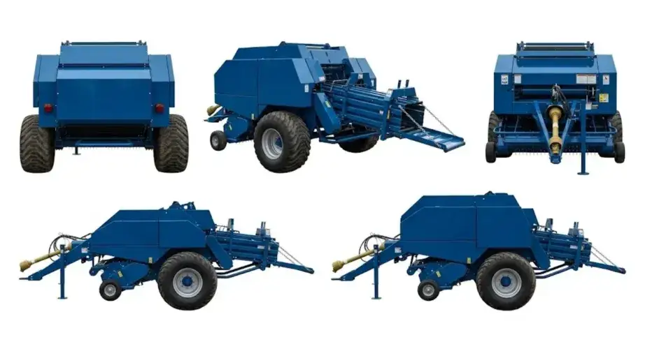
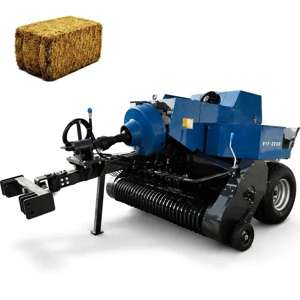
All 9YF square baler models use two D-type knotters positioned at equal spacing across the 460mm bale chamber width. Both knotters must complete their cycle simultaneously on every bale — a failure on one side produces a bale tied only on the opposite side, which typically holds its shape under light handling but collapses when the single rope is cut for feeding. When diagnosing a missed-knot problem, establish early whether it is one knotter or both failing — this distinction narrows the cause significantly.
The Six Most Common Causes of Missed Knots
A missed knot is defined as a completed bale cycle where the plunger finishes its stroke and the bale advances, but no rope is tied at the point where the knot should have formed. Six causes account for the vast majority of field missed-knot events — in rough order of how frequently each occurs:
Knotter Bill Inspection: What to Look For and When to Replace
Visual Inspection Protocol
Inspect both knotter bills at the start of every baling season and after any session where missed knots occurred. The inspection takes under two minutes per knotter and eliminates the most common source of in-field failures before they cost you bales.
- Tip geometry:The bill tip maintains a specific hook profile. Run your thumb along the tip face — it should feel sharp and consistent with no flat spots, cracks or chipped sections. Any irregularity in the tip profile affects loop grip reliability.
- Wear pattern:A correctly functioning bill shows wear only on the tip face. Wear extending up the bill body indicates a timing misalignment — the bill is contacting the twine along the wrong section of its rotation arc, which points to a cam issue rather than the bill itself.
- Rope grip test:Loop a section of your baler twine around the bill tip and apply moderate tension. The bill should grip firmly without the loop sliding. A bill that allows the loop to slide at moderate tension will fail in the field under full bale compression forces.
- Replacement threshold:Replace when the tip shows any chipping, when the grip test fails at moderate tension, or when the wear pattern has progressed more than 25% up the bill body. Bills are inexpensive relative to a session of missed knots and spoiled bales.
Knife Blade Condition
The knife cuts the twine strand after loop formation. A dull or nicked knife blade produces bales with ragged rope ends that can pull through the finished knot during bale handling — the knot appears complete at ejection but fails under stress. Test the knife edge by holding a strand of twine against the blade and pulling. A sharp knife cuts cleanly with light pressure; a dull knife requires sawing motion. Replace knife blades showing any edge rounding or visible nicks before the season rather than waiting for field failures.
Twine Tension Settings: Finding the Right Balance
How the Tension Disc Works
The tension disc on each knotter applies friction to the twine as it feeds toward the bill. The disc spring load determines how much resistance the twine experiences — higher spring load means more friction and higher twine tension at the bill. The tension specification in your operator manual gives a setting range for the crop type and twine diameter you are using. This setting interacts with bale density: a denser bale requires more twine tension to maintain loop stability during the knotter cycle.
- Twine loop slides off bill before knife engages
- Bale ejected with loose rope ends but no knot
- Twine trails behind bale in field
- Knot forms but pulls apart under light handling load
- Tight, clean knot on every bale consistently
- Rope ends trimmed cleanly with no fraying
- Bale retains rectangular shape in stack
- Both knotters tying at the same quality level
- Twine breaks at the knot point rather than being cut
- Broken strands inside the knotter housing
- Excessive twine consumption per bale
- Knotter bills showing accelerated wear on tip face
Setting Equal Tension on Both Knotters
Both tension discs must be set to the same specification. Unequal tension between the two knotters produces asymmetric bale binding — one side is tight and dense, the other is loose — causing the bale to deform toward the loose side in storage stacks. This is a common setup error after one knotter is serviced without returning the other to the same setting. After any tension adjustment, run at least five test bales and compare both rope ties before returning to full production.
Verifying with Test Bales
After any tension adjustment, the correct verification procedure is to bale a short section of windrow and pull the finished knots by hand. A correctly tensioned knot tightens further when pulled — it does not slide or pull apart with moderate hand force. A loose knot slides when pulled. A knot formed from over-tensioned twine feels brittle at the cut end and may break rather than pull tight under load.
Twine Path Inspection: Clearing Sticking, Kinking and Debris

Complete Path Inspection — Spool to Bill
The twine path runs from the spool reel, through multiple guide eyelets, around the tension disc, through the needle eye and into the knotter mechanism. Any point in this path where friction increases unexpectedly produces a knot quality problem that looks like a mechanical failure but is actually a maintenance issue. Inspect the full path at the start of each baling day:
- Spool holder:Check that the spool rotates freely on its holder. A spool that catches or sticks adds intermittent tension spikes to the path — producing random knot failures that have no consistent cause and are difficult to diagnose without removing this possibility first.
- Guide eyelets:Each eyelet should be smooth and free of burrs, rust or accumulated crop material. Use a wooden probe (not metal) to clear crop debris from eyelets — a metal tool can create the very burr that causes future problems.
- Tension disc:Clear any chaff, weed seeds or compressed crop material from around the disc and its spring. A disc that cannot close fully because of material packing provides less tension than the spring setting indicates, producing under-tensioned twine at the knotter even when the spring appears correctly set.
- Needle eye:The needle carries the twine through the bale chamber on each cycle. Its eye must be smooth — any roughness or crop build-up increases friction at the critical moment when the twine must feed freely to allow the bill to form the loop. Clear the eye with a clean cloth at every session start.
Moisture and Sisal Twine
If you use sisal (natural fibre) twine, be aware that sisal swells when wet and contracts when dry. Twine used in humid conditions — early morning baling, dew-damp windrows, humid climates — swells slightly in the guide eyelets and tension disc path, increasing friction significantly without any change to the machine settings. If knotter performance is reliable in dry afternoon conditions but poor in morning baling sessions, twine moisture is the likely cause. Switching to polypropylene twine, which does not swell with moisture, resolves this without mechanical adjustment.
Knotter Cam and Timing: When Mechanical Adjustment Is Needed
What the Cam Controls
The cam is a hardened steel lobe that rotates with the main knotter shaft and drives the bill rotation through a follower arm. The cam profile determines exactly when in the needle swing cycle the bill begins its rotation. The timing window is narrow — the bill must start rotating at the precise moment the needle presents the twine in the correct position for grip. A cam that is worn on its leading edge produces a late-rotating bill; a cam worn on its trailing edge produces an early-rotating bill. Both produce missed knots through different mechanisms.
Identifying Cam Wear
Cam wear is typically visible as a flat spot or polished depression on the lobe face where the follower arm rides. This inspection requires removing the knotter cover plate to access the cam. With the knotter at rest, rotate the main shaft slowly by hand and observe the follower arm movement — the follower should lift and fall smoothly with no hesitation or flat-tracking on the cam lobe. Any flat section on the lobe represents lost timing duration and should be measured against the manufacturer tolerance before deciding on replacement.
Timing Adjustment vs Component Replacement
Some cam wear can be compensated by adjusting the follower arm position — effectively advancing the timing to account for the worn leading edge profile. This adjustment is described in the operator manual and should be performed before replacing the cam. However, adjustment has a finite range. When cam wear has progressed beyond the adjustment limit, replacement is the correct solution — continued operation with a severely worn cam produces intermittent missed knots that cannot be reliably corrected by any other adjustment.
Twine Breaking: A Different Problem from Missed Knots
Breaking vs Missing — How to Tell the Difference
A missed knot leaves a bale with loose rope ends trailing from it — the rope ran through the cycle but did not form a knot. Twine breaking leaves a bale with one or both sides completely bare and a rope end somewhere inside the knotter housing or chamber — the rope broke before completing the cycle. This distinction matters because they have different causes and different fixes.
Check where the break occurred: a break at the knot point indicates over-tensioning or a twine strength rating insufficient for the bale density being produced. A break in the path between the spool and the needle indicates a sharp edge in the path, a kink from a spool tangle, or a weak spot in the twine from moisture or UV damage. A break at the needle eye indicates a burr on the eye or a twine-path geometry problem.
Twine Strength Rating and Bale Density
Baler twine is rated by knot strength — typically 110kg, 130kg or 165kg for small square baler applications. The correct rating depends on the bale density and bale weight you are producing. At standard hay density in a 20–25kg bale, 110kg-rated twine is adequate. At high-density settings in a 35–40kg corn stover or alfalfa bale, the knot strength requirement increases and twine rated below the requirement will break at the knot point under the compression force. If twine regularly breaks at the knot in heavy bales, verify the twine rating against the manufacturer recommendation for your density setting before replacing mechanical components.
Bale Ejected Without a Tie: Field Diagnosis Steps
Immediate Field Actions
When a bale ejects without any rope on it — not a missed knot, but completely bare — the first step is to disengage the PTO immediately. Do not continue baling. A bare-bale failure indicates that the twine supply to one or both knotters was completely interrupted during the cycle. Continuing to bale without addressing this produces a string of bare bales and potentially a tangle of loose twine in the chamber mechanism.
- Disengage PTO and stop the tractor
- Check both spool holders — is either spool empty or tangled?
- Trace the rope from the spool through the path on each side — where does the continuity end?
- Look inside the knotter housing for a rope tangle or break
- If path is clear, check the needle — has it bent or missed its full stroke?
- Re-thread the affected side per the operator manual threading diagram
- Run three test bales at reduced speed before returning to production
One-Side vs Both-Sides Bare
One side tied, one side bare: a problem specific to one of the two knotters — check that knotter path, bill and cam independently. Both sides bare: suggests the needle did not complete its stroke on this bale cycle, the main knotter drive shaft has a problem, or the trip mechanism that triggers the knotting cycle at the end of the bale length failed to engage. The trip mechanism is controlled by the star wheel — check that the star wheel rotates freely and that its cam follower contacts the trip lever correctly.
Preventive Maintenance: What to Check Before Every Session
Daily Pre-Baling Checklist (10 Minutes)
- ☐Visually inspect both knotter bill tips — no chipping or rounding
- ☐Clear all guide eyelets and the tension disc of crop debris from the previous session
- ☐Check both spool levels — never start a field with less than half a spool remaining
- ☐Verify tension disc spring compression on both knotters — equal setting on both sides
- ☐Run the needle through its stroke by hand before engaging PTO — verify free movement
- ☐Bale the first 5 bales at reduced forward speed and inspect all knots before committing to full field speed
Pre-Season Annual Service
- ☐Remove both knotter cover plates and clean the full mechanism
- ☐Inspect and replace knotter bills showing any wear on the tip face
- ☐Replace knife blades — install new blades before each season rather than testing old ones
- ☐Inspect cam lobe face for flat spots or polished wear zones
- ☐Lubricate all knotter pivot points, needle arms and cam follower per the operator manual schedule
- ☐Remove twine from both spools and store indoors — never leave twine on the machine between seasons
PTO Driveline and Gearbox References for Square Baler Setup
Correct PTO shaft length, slip clutch specification and gearbox torque rating prevent overload failures that place stress on the entire knotter drive train. Verify these parameters when connecting a baler to a new tractor or after any drivetrain component change.
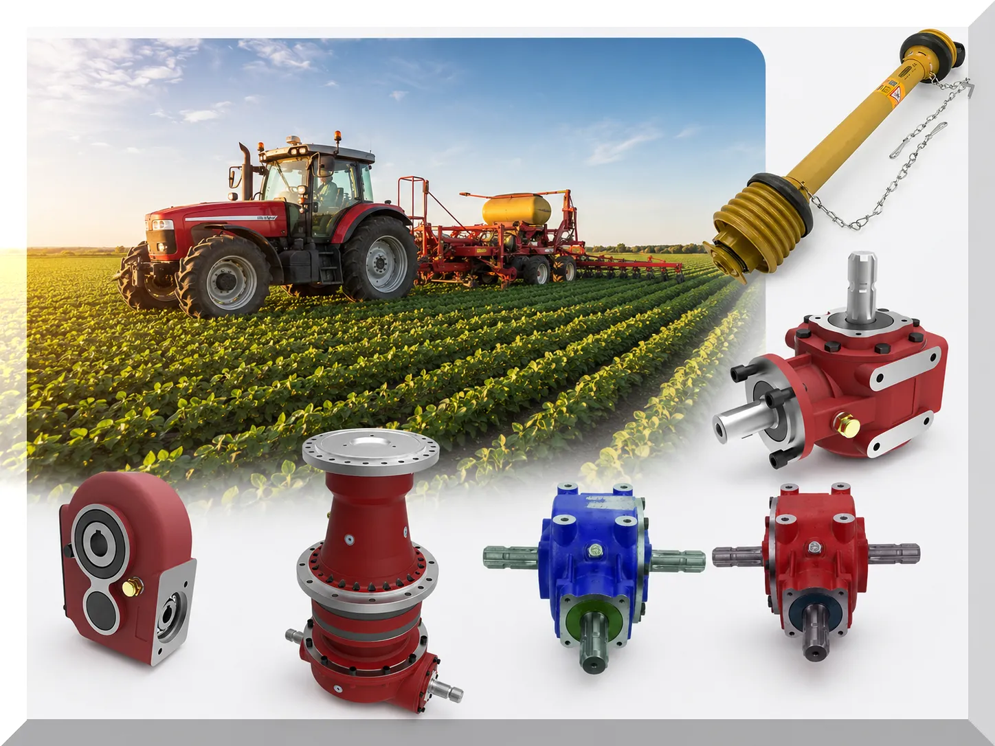
Gearbox torque ratings, PTO shaft dimensions and coupling standards: 농업용 기어박스 및 PTO 샤프트 사양
PTO driveshaft length, CV joint angle limits and safety shield condition are equally critical — a shaft that bottoms out at full compression or contacts the shield during turning places shock loads on the baler gearbox that accelerate internal wear. Driveshaft specifications for this application are covered in the PTO 구동축 및 CV 조인트 크기 가이드.
Minimum PTO shaft check: with the baler hitched at maximum tractor turn, verify the shield clears all components and the shaft does not bottom out at full compression in the telescoping section.
Frequently Asked Questions — Square Baler Knotter Troubleshooting

Need a Square Baler That Ties Reliably Every Bale?
The 9YF series uses dual D-type knotters across all five models — consistent design, consistent maintenance requirements, consistent performance. Tell us your primary crop and tractor HP and we will recommend the right model.
460×360mm auto rope baling
40HP to 99HP model range
아메리카 에버파워 사료 베일러 장비 주식회사 · 1401 21번가 R호, 새크라멘토, 캘리포니아 95811
편집자:Cxm


