الدائرة الهيدروليكية لآلة كبس البالات الدائرية: ما الذي تتحكم به وأين تتعطل؟
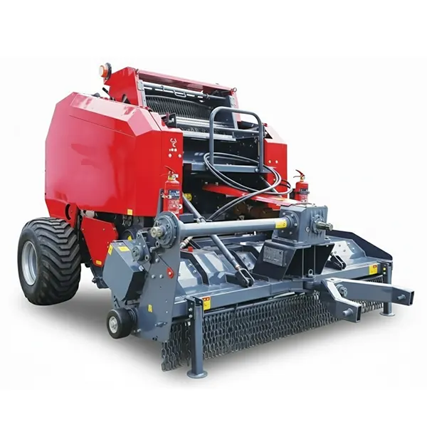
يُعدّ النظام الهيدروليكي لآلة كبس التبن الدائرية نظامًا فرعيًا ضمن واجهة الجرار مع آلة الكبس، حيث تستخدم الآلة التدفق والضغط الهيدروليكي المُزوَّد من منافذ التحكم الخلفية للجرار لتشغيل وظائفها. وعلى عكس نظام سلسلة القيادة، الذي يعمل ميكانيكيًا عبر عمود نقل الحركة، يعتمد النظام الهيدروليكي بشكل أساسي على توافر شرطين في آنٍ واحد: أولهما، أن يتطابق خرج النظام الهيدروليكي للجرار مع متطلبات دائرة آلة الكبس، وثانيهما، أن تحافظ المكونات الداخلية لآلة الكبس (الأسطوانات، والخراطيم، والوصلات، وصمامات التحكم) على سلامة الضغط في ظروف الحقل. عند اختلال أيٍّ من هذين الشرطين، تظهر أعراض التشغيل فورًا، وغالبًا ما يتم تشخيصها خطأً على أنها مشاكل في الجرار، أو في آلة الكبس، أو في الصمامات الهيدروليكية، بينما يكون السبب الحقيقي في مكون مختلف تمامًا.
السبب #3
تُصنف أعطال النظام الهيدروليكي كثالث أكثر أسباب توقف مكابس التبن شيوعًا في منتصف الموسم بعد مشاكل الحزام وأعطال السلسلة - حيث تمثل أعطال أسطوانة البوابة الخلفية والخرطوم ما يقرب من 70% من أحداث خدمة النظام الهيدروليكي
2000–3000
ضغط التشغيل النموذجي بالرطل لكل بوصة مربعة لدائرة هيدروليكية في مكبس بالات القش الدائرية - مرتفع بما يكفي بحيث ينتج عن تسرب خرطوم صغير رذاذ دقيق قادر على الاشتعال على غلاف محمل ساخن، وليس تيارًا مرئيًا يُعلن عن وجوده بأمان
ست سنوات
العمر الافتراضي الأقصى الموصى به للخراطيم الهيدروليكية بغض النظر عن مظهرها الخارجي - فالتدهور الداخلي للأنابيب الذي يُسبب التلوث وخطر التلف لا يكون مرئيًا من الخارج، مما يجعل الاستبدال بناءً على العمر هو البروتوكول الصحيح.
| الوظيفة الهيدروليكية |
نوع الدائرة |
معدل الفشل |
العرض الرئيسي عند الفشل |
| فتح/إغلاق الباب الخلفي |
أسطوانة أحادية الفعل |
الأكثر شيوعاً |
لا يفتح باب الصندوق الخلفي؛ يفتح ببطء؛ ينغلق تدريجياً بعد الفتح؛ تسرب من القضيب |
| التحكم في ارتفاع الالتقاط |
أسطوانة مزدوجة الفعل (معظم الموديلات) |
معتدل |
لا يمكن رفع/خفض الشاحنة؛ وتتحرك بشكل غير متحكم به فوق التضاريس غير المستوية |
| تعشيق السكين المقطوعة مسبقًا |
أسطوانة أحادية الفعل أو محرك هيدروليكي |
أقل شيوعاً |
لن تنغلق السكاكين أو تنكمش؛ بل تنغلق تلقائيًا |
| أداة شد لف الشبكة/الخيط |
محرك هيدروليكي (في بعض الطرازات) |
أقل شيوعاً |
شد غير منتظم للغلاف؛ انحشار أو انقطاع مادة الغلاف |
| التحكم في الكثافة/الحجرة (بعض الطرازات) |
مُجمِّع زنبركي هيدروليكي |
أقل شيوعاً |
كثافة غير متناسقة للبالات؛ تفتح حجرة التجميع قبل الأوان أو لا تفتح |
مشكلة المطابقة بين المركز المفتوح والمركز المغلق: صُممت معظم مكابس التبن الدائرية القديمة للعمل مع دوائر هيدروليكية مفتوحة المركز في الجرارات، حيث يتدفق السائل باستمرار عبر دائرة المكبس حتى في حالة عدم تشغيل أي وظيفة. أما الجرارات الحديثة فتستخدم بشكل متزايد أنظمة هيدروليكية مغلقة المركز أو أنظمة استشعار الحمل. يؤدي توصيل مكبس تبن مفتوح المركز بجرار مغلق المركز إلى زيادة مستمرة في الضغط دون وجود منفذ لعودة السائل، مما يتسبب في ارتفاع درجة الحرارة، واهتزاز صمام التحكم، وتآكل متسارع للأختام. راجع دليل تشغيل مكبس التبن لمعرفة نوع الدائرة وتأكد من توافقها مع جرارك قبل التوصيل. يُستخدم صمام التحكم في التدفق في خط الإمداد أحيانًا كحل للتحديث؛ استشر الشركة المصنعة لمكبس التبن.
اختيار السائل الهيدروليكي: النوع، والدرجة، وفترة التغيير
يُعدّ اختيار سائل الهيدروليك الخطأ الأكثر شيوعًا في صيانة أنظمة الهيدروليك في مكابس التبن. فالمشغّلون الذين يستخدمون مصطلح "سائل الهيدروليك" بشكل عام - معتبرين جميع زيوت الهيدروليك قابلة للتبديل - يُعرّضون أنفسهم لخطر تسارع تلف موانع التسرب، وفشل عدم تطابق اللزوجة، وتآكل المكونات الداخلية. ليس السائل الصحيح هو "AW46" أو "UTTO" كحلٍّ عام، بل هو تحديدًا ما يُحدّده دليل تشغيل مكبس التبن، سواءً لدائرة الجرار (في حال استخدام وحدات تحكم عن بُعد للجرار) أو للخزان المُدمج (إذا كان مكبس التبن مزوّدًا بخزان خاص به).
مكابس القش التي تستخدم الدائرة الهيدروليكية للجرار
تتصل معظم مكابس التبن الدائرية في أمريكا الشمالية بوحدات التحكم الهيدروليكية الخلفية للجرار وتستخدم سائله الهيدروليكي. في هذه الحالة، يكون "السائل الهيدروليكي المناسب للمكبس" هو ما تحدده الشركة المصنعة للجرار لنظامه الهيدروليكي. إضافة نوع سائل مختلف إلى خزان الجرار - لمجرد أن أحدهم أخبرك أن المكبس يحتاج إلى AW46 - يُلوث السائل الهيدروليكي للجرار وقد يُبطل ضمانه. الأختام الداخلية للمكبس مصممة خصيصًا للسائل الذي يوفره الجرار؛ فلا حاجة لتغييره. فترة تغيير السائل: اتبع جدول تغيير السائل الهيدروليكي الموصى به من قبل الشركة المصنعة للجرار.
مكابس مزودة بخزانات هيدروليكية ذاتية الاحتواء
تتضمن بعض طرازات مكابس التبن، وخاصةً التصاميم الأوروبية، خزانًا هيدروليكيًا مستقلًا يُملأ بشكل منفصل عن الجرار. تتطلب هذه المكابس استخدام السائل المحدد المذكور في دليل التشغيل. الأكثر شيوعًا: زيت هيدروليكي ISO VG 46 أو ما يعادله AW46 للمناطق المعتدلة؛ AW32 للعمليات في الطقس البارد (أقل من -7 درجات مئوية)؛ زيت ناقل الحركة العالمي للجرارات UTTO (UTTO) لبعض الطرازات الأوروبية. فترة التغيير: سنويًا أو كل 250-500 ساعة تشغيل، أيهما أقرب. في حال عدم توفر الدليل: يُعد زيت AW46 الخيار الآمن لمعظم ظروف التشغيل في أمريكا الشمالية، ولكن يُرجى التأكد من ذلك بالتواصل مع قسم قطع الغيار لدى الشركة المصنعة للمكبس وتزويدهم بالرقم التسلسلي.
تشخيص حالة السوائل الهيدروليكية - ما الذي يخبرك به مظهر السائل؟
حليبي / غائم
تلوث المياه. السبب: تراكم التكثيف في خزان غير مملوء بالكامل على مدار عدة مواسم تخزين؛ تلف غطاء التهوية مما يسمح بدخول الرطوبة؛ تلف مانع التسرب الخارجي مما يسمح بدخول الماء. الإجراء: تفريغ الخزان بالكامل، وشطف النظام بسائل نظيف متوافق، وإعادة ملئه بسائل جديد، وتحديد نقطة دخول الماء. لا تستخدم سائلًا ملوثًا بالماء - فالماء يعزز التآكل الداخلي، ويقلل من قوة طبقة التشحيم، ويسرع بشكل كبير من تدهور مانع التسرب.
رغوي / مهوى
ابتلاع الهواء. السبب: تسرب في خط السحب (وصلة غير محكمة في جانب الإرجاع)؛ انخفاض مستوى السائل (سحب المضخة للهواء مع السائل)؛ سرعة عالية للسائل العائد مما يُسبب تجويفًا في الخزان. الإجراء: تحقق من مستوى السائل أولًا؛ افحص وصلات جانب السحب؛ اترك السائل ليستقر وتحقق من استمرار تكون الرغوة. يُسبب السائل المُهوى استجابة إسفنجية وغير منتظمة للمُشغل ويُسرّع من تآكل المضخة.
رائحة داكنة / محترقة
التحلل الحراري. السبب: تشغيل النظام عند درجات حرارة مستمرة أعلى من النطاق المُصنّف للسائل (عادةً ما يزيد عن 180 درجة فهرنهايت لسائل AW46)؛ ضبط صمام التنفيس على درجة حرارة عالية جدًا؛ انسداد الدائرة مما يُسبب ضغطًا عكسيًا زائدًا. الإجراء: تغيير السائل؛ تحديد مصدر الحرارة. يفقد السائل المتدهور لزوجته وفعالية إضافات مقاومة التآكل، ويؤدي استمرار التشغيل إلى تسريع تآكل المكونات الداخلية.
جزيئات خشنة / معدنية
عطل في أحد المكونات الداخلية. تشير جزيئات المعدن إلى تآكل المضخة أو الصمام أو تجويف الأسطوانة. الإجراء: تغيير السائل والفلتر؛ فحص مصدر تكوّن المعدن. استمرار التشغيل يؤدي إلى انتشار جزيئات كاشطة في جميع أنحاء النظام، مما يتسبب في تلف سريع ومتزايد للمضخة والصمامات والأسطوانات في آن واحد.
تحديد مصدر التسرب: العثور على المصدر دون التسبب في حالة طوارئ طبية
يُعدّ تحديد تسرب الزيت الهيدروليكي إجراءً بالغ الخطورة، يختلف عن جميع إجراءات تشخيص صيانة مكابس التبن الأخرى: فالتسرب الهيدروليكي المضغوط عند ضغط التشغيل (2000-3000 رطل لكل بوصة مربعة) لا يبدو كتيار سائل، بل كرذاذ دقيق أو منطقة رطبة دون مصدر واضح. ويمكن للثقب الدقيق غير المرئي الذي يُكوّن هذا الرذاذ أن يحقن الزيت الهيدروليكي عبر الجلد بسرعة لا تُسبب ألمًا فوريًا، ولكنها تُؤدي إلى موت الأنسجة تدريجيًا من الداخل. وهذه إحدى أخطر آليات الإصابة في الآلات الزراعية، وأقلها فهمًا.
قاعدة أمان أساسية: اختبار الكرتون - لا تستخدم اليدين العاريتين أبدًا
تحدث إصابة الحقن الهيدروليكي عندما يدخل سائل مضغوط إلى الجسم عبر جرح قد يكون صغيرًا جدًا. يبدو الجرح طفيفًا، وغالبًا لا يكون هناك ألم فوري لأن الحقن عالي السرعة يحدث بسرعة كبيرة جدًا بحيث لا يُسجّل كإصابة عادية. في غضون ساعات، يتسبب السائل المحقون في نخر تدريجي للأنسجة قد يتطلب بترًا، وقد تسبب في وفيات. يمكن أن يحدث هذا مع أي نظام هيدروليكي تحت ضغط، بما في ذلك دائرة مكبس التبن الدائري عند ضغط يزيد عن 2000 رطل لكل بوصة مربعة.
حدد مكان التسريبات باستخدام اختبار الكرتون: أمسك قطعة من الكرتون الجاف على بُعد ذراع (أكثر من 45 سم) من منطقة التسريب المشتبه بها بينما يكون النظام تحت ضغط. يُخلّف التسريب الصغير بقعة رطبة على الكرتون عند نقطة الاختراق. لا تفحص التسريب المشتبه به بأصابعك أبدًا، حتى مع ارتداء القفازات. أي إصابة مشتبه بها ناتجة عن حقن هيدروليكي تُعد حالة طبية طارئة - توجه إلى قسم الطوارئ فورًا بغض النظر عن وجود ألم. يجب إبلاغ أطباء الطوارئ بأن إصابة الحقن الهيدروليكي هي الآلية المشتبه بها؛ فبروتوكولات علاج الجروح القياسية غير كافية.
قليل
عاجل
تسرب خارجي - ثابت، بدون تقطير مرئي. سطح رطب أو مبلل على وصلة أو قضيب أسطوانة دون وجود تسريب سائل فعلي. يشير هذا عادةً إلى تلف في مانع التسرب في جزء منخفض الضغط أو ساكن من الدائرة. يمكن مراقبة هذه الحالة خلال الموسم الحالي بإجراء فحوصات يومية؛ ويُنصح بجدولة الإصلاحات خلال فترة توقف الموسم. راقب تطور التسريب إلى تسريب فعلي.
معتدل
عاجل
التنقيط النشط - قطرات تتشكل وتسقط من الوصلة أو الخرطوم. تلف في مانع التسرب أو الوصلة تحت ضغط منخفض إلى متوسط، ويظهر عادةً في نهاية العملية عند انخفاض ضغط النظام. يجب الإصلاح قبل جلسة التعبئة التالية، حيث أن استمرار التشغيل يُعرّض مكان التسرب لخطر ملامسة المكونات الساخنة، مما قد يؤدي إلى نشوب حريق. حدد مصدر التسرب عند تخفيف ضغط النظام وفصل وحدة نقل الحركة.
عالي
عاجل
تيار مضغوط أو رذاذ - رذاذ مرئي أو ضباب ناعم في ظل ظروف التشغيل. يشكل هذا خطرًا حقيقيًا للحريق إذا لامس الرذاذ أي جزء ساخن؛ كما أنه الوضع الأكثر احتمالًا للتسبب في إصابات ناتجة عن حقن الزيت الهيدروليكي. أوقف التشغيل فورًا، وافصل وحدة نقل الحركة، وخفف ضغط النظام، وحدد مصدر التسريب فقط بعد التأكد من انخفاض ضغط النظام بالكامل. استخدم اختبار الكرتون للكشف عن تسريبات الرذاذ، وليس الفحص البصري عن قرب.
فحص واستبدال خطوط الهيدروليك
تتمتع الخراطيم الهيدروليكية بعمر افتراضي محدد لا يمكن التنبؤ به بمجرد الفحص البصري. الغلاف الخارجي الظاهر هو غلاف واقٍ يغطي طبقات التقوية والأنبوب الداخلي - الذي ينقل السائل فعليًا - والذي قد يتلف بفعل الحرارة، أو عدم التوافق الكيميائي، أو الانثناء المتكرر دون ظهور أعراض خارجية واضحة. لهذا السبب، يُعد الاستبدال بناءً على العمر الافتراضي هو المعيار الصحيح، وليس بناءً على المظهر.
معايير الفحص البصري - استبدل أي معايير موجودة إن وجدت
- تشقق أو تصدع الغلاف الخارجي - أي تشقق سطحي يشير إلى التدهور الناتج عن الأشعة فوق البنفسجية/التقادم
- يشير الانتفاخ في أي مكان على طول الخرطوم إلى تلف الأنبوب الداخلي أو تلف ناتج عن الضغط عند تلك النقطة.
- علامات الاحتكاك حيث يحتك الخرطوم بالمعدن - استبدله وأعد توجيهه
- انثناء مرئي - خرطوم منثني يؤدي إلى تدهور دائم في التدفق والسلامة الهيكلية
- تغير اللون نتيجة التعرض للحرارة (غلاف خارجي بني أو متصلب)
- العمر الذي يزيد عن 6 سنوات - بغض النظر عن المظهر، يجب استبدالها عند بلوغها الحد الأقصى لعمر الخدمة وهو 6 سنوات
قواعد التوجيه التي تمنع الفشل المبكر
قاعدة التراخي 10%: يجب أن يزيد طول كل خرطوم بمقدار 10% عن المسافة المستقيمة بين وصلاته. يتعرض الخرطوم الممتد بالكامل عند أقصى حركة للمشغل لإجهاد شد يُسرّع من تلف الوصلات. مسافة فاصلة للأجزاء الساخنة: يجب ألا يمر أي خرطوم على مسافة تقل عن 3 بوصات من غلاف المحمل أو عمود نقل الحركة أو أي مكون يولد حرارة أثناء التشغيل. الحماية من الاحتكاك: استخدم أغطية واقية على الخراطيم التي تمتد على طول حواف الهيكل أو عبر المناطق التي قد تتعرض لمخلفات المحاصيل. للاطلاع على مواصفات عمود إدارة الطاقة وعلبة التروس التي تحدد متطلبات الضغط الهيدروليكي، انظر مواصفات مكونات علبة التروس الزراعية ومجموعة نقل الحركة PTO.
يشمل الفحص الموسمي الكامل للصيانة فحص الخراطيم الهيدروليكية وخدمة السلاسل والأحزمة والمحامل. قائمة فحص الصيانة الموسمية لآلة كبس البالات الدائرية.
خدمة أسطوانة باب الصندوق الخلفي: بروتوكول إعادة البناء خطوة بخطوة
يُعدّ أسطوانة الباب الخلفي أكثر المكونات الهيدروليكية التي تحتاج إلى صيانة في مكبس التبن الدائري، فهي تُشغّل كل بالة على حدة (فتح وإغلاق لكل بالة)، وتتعرض مباشرةً لمخلفات المحاصيل والرطوبة والصدمات الميكانيكية الناتجة عن وزن الباب الخلفي. يُعدّ استبدال مانع التسرب الحل الأمثل لمعظم أعطال أسطوانة الباب الخلفي، وهي عملية يُمكن لفنيّ مُختصّ ميكانيكيًا إنجازها في غضون ساعتين إلى ثلاث ساعات باستخدام أدوات بسيطة ومجموعة مانعات التسرب المُرفقة من الشركة المُصنّعة.
استبدال مانع تسرب أسطوانة الباب الخلفي - إجراء من 10 خطوات
1
قم بتفريغ الضغط الهيدروليكي بالكامل. افصل نظام نقل الحركة (PTO) وحرّك ذراع التحكم الهيدروليكي للباب الخلفي عدة مرات حتى يتوقف كل تحرك المشغل ولا يُبدي الذراع أي مقاومة. افصل وصلات التوصيل السريع الهيدروليكية للجرار. أصبح النظام الآن عند ضغط صفري - لا تتابع حتى تتأكد من ذلك.
2
قم بسحب قضيب الأسطوانة إلى أقصر وضع له قبل إزالته. يفقد الأسطوانة المنكمشة كمية أقل من السائل أثناء الإزالة، كما يسهل التعامل معها على طاولة العمل. إذا لزم دعم الباب الخلفي خارجيًا للسماح بسحبه دون حمل، فاستخدم سلسلة أو رافعة - لا تترك الباب الخلفي أو إطاره مدعومًا فقط بالأسطوانة المنكمشة أثناء عملية الصيانة.
3
ضع وعاءً لتصريف السوائل وقم بإزالة وصلات الخراطيم الهيدروليكية من منافذ الأسطوانة. استخدم مفاتيح ربط الصواميل المتوهجة المناسبة - وليس مفاتيح الربط المفتوحة - لتجنب تلف الوصلات. من المتوقع تسرب بعض السوائل من الخراطيم ومنافذ الأسطوانات؛ لذا قم بتغطية جميع الفتحات بقطع قماش نظيفة أو أغطية منافذ هيدروليكية لمنع التلوث.
4
قم بإزالة الأسطوانة من آلة التجميع عن طريق سحب دبابيس التثبيت. تُثبّت المسامير عادةً بحلقات تثبيت أو مسامير أسطوانية - لذا جهّز كماشة حلقات التثبيت ومثقبًا. ادعم الأسطوانة أثناء إزالة المسامير؛ فالأسطوانة الهيدروليكية أثقل مما تبدو عليه.
5
قم بتثبيت الأسطوانة في ملزمة الطاولة باستخدام أغطية فك ناعمة. احمِ سطح القضيب، فأي خدش أو شق فيه سيتلف مانع التسرب الجديد فورًا. ويمكن استخدام قطعة من خرطوم مطاطي لحماية القضيب في حال عدم توفر فكوك ناعمة.
6
قم بإزالة صامولة الغدة باستخدام مفتاح ربط أو مفتاح ربط شريطي. تُثبّت صامولة التثبيت مجموعة المكبس داخل الأسطوانة. عادةً ما تكون مُحكمة الربط (100-250 قدم-رطل لأسطوانات مكابس القش النموذجية)؛ ويُساعد وضع زيت التشحيم على السنون. تجنّب استخدام المثقاب والمطرقة، فسطح صامولة التثبيت مُصنّع بدقة عالية، وأي تلف فيه يُؤدي إلى تلف مانع التسرب.
7
اسحب مجموعة المكبس للخارج وضع جميع المكونات بالترتيب على سطح نظيف. صوّر ترتيب الأختام قبل إزالة أي منها، فترتيب كل ختم واتجاهه أمران بالغا الأهمية. يجب أن تتطابق مجموعة الأختام تمامًا مع قطر تجويف الأسطوانة وقطر القضيب. اطلبها بناءً على رقم طراز الأسطوانة، وليس بناءً على القياسات التقريبية.
8
استبدل جميع الحلقات المانعة للتسرب في المجموعة - كل حلقة مانعة للتسرب، وليس فقط الحلقات التالفة بشكل واضح. استبدال كل مانع تسرب على حدة ليس إجراءً سليماً؛ فإذا تعطل أحد موانع التسرب بسبب التقادم أو التعرض للملوثات، فإن باقي الموانع تكون في مرحلة مماثلة من عمرها الافتراضي. يجب تزييت جميع موانع التسرب الجديدة بسائل هيدروليكي نظيف قبل تركيبها، وليس بشحم البترول الذي يحتوي على زيوت معدنية غير متوافقة مع مواد موانع التسرب الهيدروليكية.
9
أعد التجميع بترتيب عكسي؛ اربط صامولة الغدة وفقًا للمواصفات. أعد تركيب المسامير باستخدام حلقات تثبيت جديدة (لا تعيد استخدام حلقات التثبيت أبدًا، لأنها تفقد قوة التثبيت بعد إزالتها). أعد توصيل خراطيم المياه وشدها يدويًا، ثم استخدم مفتاح ربط لإتمام ربع الدورة الأخيرة على وصلات JIC.
10
أعد توصيل نظام الهيدروليك للجرار وقم بتشغيل الباب الخلفي 10 مرات قبل التحقق من وجود تسريبات. تحتاج موانع التسرب إلى عدة دورات لتثبيتها بشكل صحيح. تحقق من وجود تسريبات خارجية من القضيب وانحراف (انخفاض الباب الخلفي ببطء من وضع الفتح) بعد كل دورة. يُعدّ انحراف طفيف في أول دورتين أو ثلاث دورات أمرًا طبيعيًا أثناء تثبيت موانع التسرب؛ أما الانحراف المستمر بعد 10 دورات فيشير إما إلى مشكلة في مانع التسرب الداخلي أو مشكلة في صمام التثبيت الهيدروليكي - راجع
دليل استكشاف أعطال مكبس بالات القش الدائرية لتشخيص الانحراف.
مواصفات الضغط وصمام التنفيس: ماذا تعني الأرقام؟
لا يمثل ضغط النظام الهيدروليكي في مكبس التبن الدائري قيمة واحدة، بل هو نطاق محدد بضغط التشغيل أثناء الأداء الطبيعي وضغط تخفيف الضغط عند أقصى حمل. يُعد فهم كلا القيمتين، والقدرة على تمييز أعراض كل من الضغط الزائد والضغط المنخفض، أمرًا بالغ الأهمية لتشخيص المشكلات الهيدروليكية التي لا تغطيها أدلة استكشاف الأعطال بشكل كامل.
قيم الضغط النموذجية
ضغط التشغيل العادي: 1500-2200 رطل لكل بوصة مربعة أثناء فتح/إغلاق الباب الخلفي
ذروة الضغط (إخراج البالة): 2200-2800 رطل لكل بوصة مربعة للبالات الثقيلة
ضبط صمام تخفيف الضغط في النظام: 2500–3200 رطل لكل بوصة مربعة (ضبط المصنع - لا تقم بالتعديل بدون مواصفات الشركة المصنعة)
ضغط مخرج التحكم عن بعد للجرار: يجب أن يطابق أو يتجاوز متطلبات دائرة مكبس البالات
تشخيص الأعراض والضغط
بطء في الحركة، ضعف في العمليات: انخفاض ضغط الدائرة الكهربائية - تحقق من ضغط مخرج التحكم عن بعد في الجرار، وتحقق من عدم وجود انسدادات في الخراطيم.
صوت صمام التنفيس (أزيز/خشخشة تحت الحمل): يعمل النظام عند مستوى تخفيف الضغط أو بالقرب منه - تحقق من وجود ضغط خلفي زائد أو انسداد.
أعطال الخراطيم عند الوصلات: زيادة الضغط أو ارتفاعات الضغط المفاجئة — تحقق من أن صمام التنفيس ليس مضبوطًا على قيمة أعلى من مواصفات الشركة المصنعة.
ارتفاع درجة حرارة السائل: ضغط خلفي مفرط، أو عدم تطابق نوع الدائرة، أو دورات تشغيل مفرطة تحت الحمل
تسربات الزيت الهيدروليكي وخطر الحريق: العلاقة التي لا يمكن تجاهلها
يرتبط النظام الهيدروليكي لآلة كبس التبن الدائرية وخطر نشوب حريق فيها بآلية بسيطة بمجرد فهمها، ولكنها غالبًا ما تُغفل لأن صيانة الأنظمة الهيدروليكية والوقاية من الحرائق تُعاملان عادةً كموضوعين منفصلين. إن خرطومًا هيدروليكيًا به ثقب صغير متسرب، يمر بالقرب من غلاف محمل تالف، ليس مشكلة صيانة هيدروليكية، بل هو مصدر حريق. يتفتت رذاذ السائل المتسرب حتى من ثقب صغير جدًا (1/16 بوصة) عند ضغط 2500 رطل لكل بوصة مربعة إلى جزيئات دقيقة بما يكفي للاشتعال عند ملامستها سطحًا معدنيًا فوق نقطة اشتعال السائل (حوالي 380-450 درجة فهرنهايت لـ AW46).
سلسلة اشتعال الحريق
تشغيل المحمل بدون تشحيم كافٍ ← ترتفع درجة حرارة المحمل إلى 350-500 درجة فهرنهايت ← علامة احتكاك على خرطوم هيدروليكي قريب (نتيجة الاهتزاز أو تراكم المحاصيل) تُحدث ثقبًا صغيرًا ← يخرج رذاذ هيدروليكي بضغط 2500 رطل لكل بوصة مربعة ويلامس غلاف المحمل الساخن ← اشتعال فوري. هذا التسلسل ليس نادرًا، بل هو الآلية الكامنة وراء جزء كبير من حرائق مكابس القش الموثقة في تقارير حوادث الخسائر الزراعية. الإجراء الوقائي: فحص كل خرطوم بحثًا عن علامات احتكاك بالقرب من كل محمل خلال الفحص قبل الموسم وفي منتصف الموسم. تتطلب علامات الاحتكاك استبدال الخرطوم وإعادة توجيهه فورًا.
الفحص الهيدروليكي لمخاطر الحريق قبل الموسم
يشمل الفحص السنوي ما يلي: تتبع كل خرطوم هيدروليكي من وصلة إلى أخرى، والتحقق من وجود علامات احتكاك أو انثناءات أو قربه من محامل الكراتين أو الأجزاء الساخنة. يُرجى إيلاء اهتمام خاص للخراطيم الموجودة على جانب عمود إدارة الطاقة (PTO) في آلة التجميع، حيث تكون كثافة المحامل أعلى ودرجات الحرارة أعلى ما يمكن أثناء التشغيل. يوجد بروتوكول الوقاية من الحرائق الكامل - بما في ذلك فحص الخراطيم الهيدروليكية كخطوة متكاملة لتقييم مخاطر الحريق - في... دليل الوقاية من الحرائق والسلامة في مكابس البالات الدائرية.
التخزين الشتوي: حماية النظام الهيدروليكي خلال فترة عدم الاستخدام
يتطلب النظام الهيدروليكي المخزن بشكل صحيح الحد الأدنى من الصيانة عند بدء التشغيل في الربيع. أما النظام المخزن بشكل خاطئ - مع تمديد الأسطوانات، أو عدم ملء خزانات السوائل بشكل كافٍ، أو تلف أغطية التهوية - فسيصل إلى موسم الحصاد التالي متضررًا من تلف الأختام، وتلوث الرطوبة، وتآكل المحامل، وهي مشاكل كان من الممكن تجنبها بصيانة لمدة 20 دقيقة فقط في نهاية الموسم.
قم بسحب جميع الأسطوانات قبل التخزين
يؤدي تعرض قضيب الأسطوانة للهواء الخارجي وتقلبات درجات الحرارة لمدة تتراوح بين 4 و6 أشهر أثناء التخزين إلى ظهور طبقة أكسدة سطحية (صدأ) تعمل كصنفرة على مانع التسرب عند تشغيل الأسطوانة لأول مرة في الموسم التالي. لذا، يجب سحب جميع الأسطوانات بالكامل (إغلاق الباب الخلفي، وخفض ذراع الالتقاط) قبل وضع آلة التجميع في المخزن. أما بالنسبة للأسطوانات التي لا يمكن سحبها بالكامل بسبب تصميم آلة التجميع، فيُنصح بتغطية أسطح القضبان المكشوفة بطبقة رقيقة من سائل هيدروليكي نظيف أو فازلين.
مستوى السائل والعناية بالخزان
بالنسبة لمكابس التبن ذات الخزانات المغلقة: املأ الخزان حتى العلامة الكاملة قبل التخزين. الخزان الممتلئ لا يترك مساحة للهواء لتكوّن التكثيف. الخزان نصف الممتلئ يُنشئ سطحًا فاصلًا بين الهواء والسائل، مما يُؤدي إلى تلوث مياه التكثيف خلال فترة التخزين، خاصةً في بيئة تخزين دافئة نهارًا وباردة ليلًا. افحص غطاء/فلتر التهوية واستبدله إذا كان تالفًا؛ فهذا هو المسار الرئيسي لدخول الرطوبة إلى الخزان حتى لو كان محكم الإغلاق.
دوران السوائل في منتصف فترة التخزين
إذا تم تخزين مكبس التبن لأكثر من ستة أشهر، فقم بتوصيله بجرار وتشغيل وظائفه الهيدروليكية مرة واحدة - لمدة خمس دقائق من تشغيل جميع المشغلات - في منتصف فترة التخزين تقريبًا. هذا يُساعد على تدوير السائل لتغطية جميع الأسطح الداخلية، ويمنع التآكل الداخلي الناتج عن الضغط الساكن، ويُحسّن أداء موانع التسرب لمنع جفافها وتشققها بسبب الضغط الساكن لفترات طويلة. يُنصح بجدولة هذا الإجراء كجزء من فحص المعدات في منتصف فصل الشتاء، وليس كمفاجأة عند بدء التشغيل في الربيع.
ال نماذج مكابس البالات الدائرية تتوفر أنظمة ذات مواصفات أسطوانات هيدروليكية محكمة الإغلاق وتصميم دائرة مغلقة يقلل من خطر التكثيف أثناء التخزين خارج الموسم، وذلك للعمليات التي تتطلب تخزينًا موسميًا ممتدًا. يُعدّ دمج خدمة النظام الهيدروليكي جزءًا من جدول الصيانة الموسمية الكامل، والذي يشمل جدول الصيانة الكامل قبل الموسم.
الأسئلة الشائعة حول النظام الهيدروليكي لآلة كبس البالات الدائرية
ما نوع سائل الهيدروليك الذي يجب أن أستخدمه في مكبس القش الدائري الخاص بي؟+
للحصول على الإجابة الصحيحة، يجب معرفة كيفية توصيل مكبس التبن بالنظام الهيدروليكي. إذا كان مكبس التبن متصلاً بوصلات النظام الهيدروليكي الخلفية للجرار دون وجود خزان مستقل، فاستخدم نفس السائل الذي يحدده الجرار لنظامه الهيدروليكي، ولا تستخدم نوعًا آخر. أما إذا كان مكبس التبن مزودًا بخزان مستقل يُملأ بشكل منفصل، فراجع دليل تشغيل المكبس لمعرفة مواصفات السائل المناسبة. تُوصي معظم مكابس التبن في أمريكا الشمالية المزودة بخزانات مستقلة باستخدام زيت هيدروليكي AW46 (ISO VG 46) للمناطق المعتدلة، بينما قد تستخدم مكابس التبن في المناطق الباردة زيت AW32. غالبًا ما تُوصي مكابس التبن الأوروبية باستخدام زيت ناقل الحركة العالمي للجرارات (UTTO). في حال عدم توفر دليل التشغيل، تواصل مع الشركة المصنعة للمكبس مع ذكر الطراز والرقم التسلسلي، حيث يمكن لفريق الدعم الفني تزويدك بمواصفات السائل الصحيحة. استخدام السائل الخاطئ ليس بالأمر الهين. يتسبب ذلك في انتفاخ الختم (تسبب الأختام كبيرة الحجم الالتصاق)، أو انكماش الختم (تسبب الأختام صغيرة الحجم التسريبات)، أو عدم توافق الإضافات مما يؤدي إلى تسريع تآكل المضخة.
باب صندوق آلة تجميع القش لا يبقى مفتوحًا - هل المشكلة في الأسطوانة أم في صمام الإغلاق؟+
انزلاق الباب الخلفي - أي نزول الباب الخلفي ببطء من وضع الفتح الكامل عند وضع ذراع التحكم في وضع الحياد - ينتج عن أحد سببين، وتحديد أحدهما يُحدد الإصلاح الصحيح. للاختبار: مع فتح الباب الخلفي وتشغيل الجرار مع وضع ذراع التحكم في وضع الحياد، افصل وصلات التوصيل السريع الهيدروليكية للجرار. إذا استمر الباب الخلفي في الانزلاق: فهذا يعني وجود تسريب داخلي في مانع التسرب في الأسطوانة نفسها (يتجاوز السائل المكبس ويتدفق من حوله). إذا توقف الانزلاق عند فصل الوصلات: فالتسريب في صمام الاحتفاظ الهيدروليكي أو صمام التحكم، وليس في الأسطوانة (يعود السائل إلى الجرار عبر صمام فحص معيب). لاختبار مانع تسرب الأسطوانة، قم بإزالة الأسطوانة وسدّ كلا المنفذين - إذا تراجع القضيب تحت الحمل مع سدّ كلا المنفذين، فهذا يعني تلف مانع تسرب المكبس. في معظم الحالات، يمكن تقييم كلا الاحتمالين (مانع تسرب الأسطوانة وصمام الاحتفاظ) قبل طلب قطع الغيار عن طريق إجراء اختبار فصل الجرار هذا أولاً.
كيف يمكنني العثور على تسرب هيدروليكي لا أستطيع رؤيته؟+
أكثر طريقتين عمليتين في الميدان هما اختبار الصبغة فوق البنفسجية واختبار الكرتون. بالنسبة لطريقة الصبغة فوق البنفسجية: أضف 30-60 مل من صبغة سائل هيدروليكي فلورية فوق بنفسجية إلى الخزان (للمكابس ذات الخزانات المستقلة) أو إلى خزان الزيت الهيدروليكي للجرار (للأنظمة المتصلة بالمكابس بالجرارات). شغّل النظام لمدة 15-30 دقيقة في ظروف التشغيل العادية. أوقفه واستخدم مصباحًا يدويًا فوق بنفسجيًا لفحص جميع الوصلات والخراطيم وقضبان الأسطوانات وأجسام الصمامات - ستتوهج الصبغة الصفراء المخضرة الفلورية في مكان التسريب حتى لو كان التسريب بطيئًا ولم تكن هناك بقع رطبة مرئية بالعين المجردة. بالنسبة لاختبار الكرتون: أمسك ورقة كبيرة من الكرتون الجاف على مسافة ذراع بالقرب من مناطق التسريب المشتبه بها أثناء تشغيل النظام. تحدد المناطق الرطبة على الكرتون الموقع العام. بالنسبة للتسريبات الصغيرة جدًا في الوصلات المضغوطة، تكون طريقة الصبغة فوق البنفسجية أكثر موثوقية. لا تستخدم يديك أو أصابعك أبدًا لفحص أماكن التسريب المشتبه بها - خطر الإصابة بالحقن الهيدروليكي عند ضغط 2500 رطل لكل بوصة مربعة حقيقي وشديد.
هل يمكنني إصلاح خرطوم هيدروليكي مؤقتًا في الموقع؟+
يُعدّ الإصلاح الميداني المؤقت لتسرب منخفض الضغط عند إحدى الوصلات مقبولاً: شدّ الوصلة، واستبدل الحلقة المطاطية أو حلقة منع التسرب إن أمكن الوصول إليها. أما في حالة تلف جسم الخرطوم (شق، ثقب صغير، أو انتفاخ)، فلا يوجد إصلاح مؤقت آمن. المنتجات التي تُسوّق على أنها "شريط إصلاح الخراطيم الهيدروليكية" أو "شريط ذاتي الالتحام" لا تتحمل ضغوط التشغيل الهيدروليكية (أكثر من 2000 رطل لكل بوصة مربعة) وتُعطي شعوراً زائفاً بالأمان يدفع المشغلين إلى الاستمرار في استخدام نظام خطير. يجب استبدال الخرطوم التالف قبل استئناف التشغيل. الحل العملي الميداني: حمل مجموعة من وصلات التوصيل السريع للخراطيم الهيدروليكية وقطعة من الخرطوم الهيدروليكي المناسب في صندوق أدوات الجرار خلال موسم الحصاد. بالنسبة للخرطوم الأكثر عرضة للتلف في مكبس التبن (عادةً خط إمداد أسطوانة الباب الخلفي)، احمل خرطوماً بديلاً جاهزاً مقطوعاً بالطول المناسب. يُعدّ سعر الخرطوم الاحتياطي الجاهز ($40–$80) مبلغًا زهيدًا مقارنةً بتكلفة مكالمة إصلاح طارئة أو خسارة يوم كامل من عمليات التعبئة. يُرجى ملاحظة أن إصلاحات التجاوز والتحويل باستخدام خراطيم ذات مقاسات صغيرة أو وصلات غير مُصنّفة من متجر المستلزمات الزراعية ليست بدائل آمنة، إذ قد تتعطل تحت الضغط في أماكن غير متوقعة.
كم مرة يجب تغيير سائل الهيدروليك في مكبس القش المزود بخزان خاص به؟+
يُوصى بتغيير الزيت سنويًا أو بعد 250-500 ساعة تشغيل (أيهما أقرب) لمعظم مكابس التبن ذات الخزانات المدمجة. يُنصح بتغيير الزيت في وقت أقرب في الحالات التالية: إذا بدا الزيت عكرًا أو حليبيًا (تلوث بالماء - يجب تغييره فورًا، ولا يُنصح بمواصلة التشغيل)؛ إذا كان لون الزيت داكنًا أو تنبعث منه رائحة احتراق (تلف حراري - يجب تغيير الزيت والتحقق من مصدر الحرارة)؛ أو إذا لم يتم تغيير الزيت لأكثر من عامين بغض النظر عن عدد ساعات التشغيل (تتلاشى إضافات الزيت الهيدروليكي بفعل الأكسدة حتى مع الاستخدام الخفيف). يُتيح لك تغيير الزيت سنويًا قبل موسم التبن - بدلًا من بعده - ميزة بدء الموسم بزيت نظيف وفحص مستوى الزيت في الخزان خلال نفس عملية الصيانة. يُنصح بإجراء فحص للفلتر (إذا كان مكبس التبن مزودًا بفلتر لخط الإرجاع) عند تغيير الزيت، حيث أن انسداد الفلتر يُسبب ضغطًا عكسيًا يؤدي إلى ارتفاع درجة الحرارة حتى مع استخدام زيت نظيف. إذا كنت غير متأكد مما إذا كانت آلة التجميع الخاصة بك تحتوي على خزان مستقل: عادةً ما تحتوي آلات التجميع المزودة بخزان هيدروليكي خاص بها على نافذة رؤية لمستوى السائل أو مقياس على خزان منفصل ليس هو الجرار؛ إذا كان بإمكانك الوصول إلى الوظائف الهيدروليكية فقط عن طريق الاتصال بأجهزة التحكم عن بعد الخاصة بالجرار ولم ترَ أي خزان منفصل، فإن آلة التجميع الخاصة بك تستخدم نظام الجرار.
لماذا ترتفع درجة حرارة النظام الهيدروليكي لآلة تجميع القش الخاصة بي أثناء التشغيل؟+
تتعدد الأسباب الرئيسية لارتفاع درجة حرارة النظام الهيدروليكي في مكبس التبن الدائري، وهي مرتبة من الأكثر شيوعًا إلى الأقل. أولًا: عدم توافق نوع الدائرة - يؤدي توصيل مكبس تبن مفتوح المركز بنظام هيدروليكي لجرار مغلق المركز إلى ضغط مستمر دون مسار عودة، مما يولد حرارة مستمرة. وهذا هو السبب الأكثر شيوعًا لارتفاع درجة الحرارة المستمر في مكابس التبن المتصلة بجرارات حديثة حلت محل معدات قديمة. ثانيًا: ضبط صمام التنفيس على قيمة عالية جدًا - يؤدي ضبط صمام التنفيس على قيمة أعلى من المواصفات الصحيحة إلى عمل النظام بضغط زائد، مما يحول الطاقة إلى حرارة. ثالثًا: انسداد خط العودة - يؤدي انسداد المرشح أو صغر حجم خرطوم العودة أو ضيق مسار العودة إلى توليد ضغط عكسي يولد حرارة في جميع أنحاء النظام. رابعًا: كثرة دورات تشغيل المشغل - تولد بعض ميزات مكبس التبن التي يتم تشغيلها بشكل متكرر (رفع/خفض وحدة الالتقاط على الطرق الوعرة، عمليات البوابة الخلفية المتكررة بمعدلات عالية) حرارة أسرع من قدرة النظام على تبديدها. خامسًا: لزوجة السائل غير المناسبة - يؤدي السائل شديد اللزوجة عند درجة حرارة التشغيل إلى مقاومة تدفق تتحول إلى حرارة. التشخيص المنهجي: ابدأ بالتحقق من توافق الدائرة الهيدروليكية بين الجرار وآلة التجميع؛ ثم تحقق من ضبط صمام التنفيس وفقًا لمواصفات الشركة المصنعة؛ ثم افحص فلتر العودة وخراطيم جانب العودة للتأكد من عدم وجود أي انسداد. يتطلب أسلوب استكشاف الأخطاء وإصلاحها لكل عطل هيدروليكي اختبارًا منهجيًا للدائرة لكل مكون على حدة.