
Todos los ajustes del anudador deben realizarse con la toma de fuerza del tractor completamente desconectada y el motor apagado. El mecanismo del anudador, bajo tensión de resorte, puede cerrarse bruscamente con fuerza si se gira manualmente algún componente. Mantenga los dedos alejados de la cara del gancho y la punta de la aguja durante el ajuste. Solo después de realizar todos los ajustes y volver a colocar las protecciones, se debe volver a conectar la toma de fuerza para realizar la prueba de empacado.
Cómo funciona el anudador tipo D: Los seis componentes
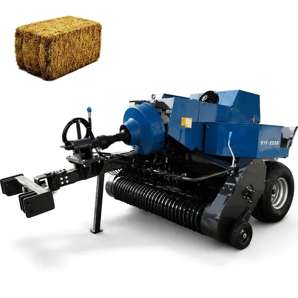
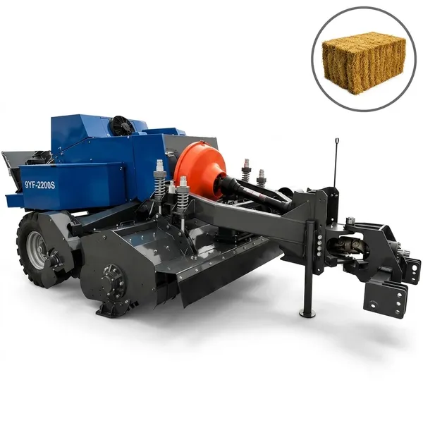
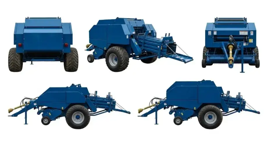
Todo diagnóstico de un nudo mal hecho comienza por saber qué componente es el responsable. El anudador doble tipo D de todos los modelos de la serie 9YF utiliza seis componentes que interactúan entre sí; cada uno tiene una función específica y un modo de fallo específico cuando está desajustado.
Gancho giratorio que forma el lazo del nudo. Su mordaza se abre para capturar el hilo suministrado por la aguja, se cierra para formar el lazo y, a continuación, este se desliza sobre la cuerda del fardo para formar el nudo final. La sincronización y el perfil de la punta son cruciales.
Se desliza sobre la leva de accionamiento que controla la sincronización de la rotación del gancho. La holgura entre el seguidor y la leva determina la precisión de la sincronización del gancho con respecto al ciclo de accionamiento principal.
Brazo que suministra un bucle de hilo desde la bobina hasta el gancho para plumas en la fase correcta del ciclo de accionamiento principal. La posición de la punta de la aguja en su recorrido máximo debe alinearse con precisión con la apertura de la mordaza del gancho para plumas.
Mantiene una presión constante sobre el hilo entre la bobina y el anudador. Controla la geometría del bucle a medida que se forma alrededor del gancho: si está demasiado apretado, se produce un bucle que se rompe; si está demasiado flojo, se produce un bucle irregular que el gancho no puede formar correctamente.
Mantiene en posición el tramo fijo de cuerda durante el ciclo de formación del nudo, de modo que la podadera pueda formar el lazo alrededor de una sección de cuerda estable en lugar de una en movimiento.
Corta el cordel una vez que el nudo esté completamente formado. El momento preciso es crucial: si se corta antes de que se forme el nudo, el extremo de la cuerda quedará suelto y sin anudar; si se corta demasiado tarde, se producirá una tensión excesiva que puede romper el cordel en el punto del nudo.
Herramientas necesarias para el ajuste del anudador
La secuencia de ajuste: el orden no es intercambiable.
Los seis ajustes del anudador interactúan entre sí. Ajustar la aguja antes de que los discos de tensión estén correctamente colocados implica que la alineación de la aguja se establece con respecto a una tensión de hilo no representativa, lo que requiere una realineación después del ajuste de los discos. Siga esta secuencia al pie de la letra:
1
2
3
4
5
6
Paso 1: Ajuste del disco de tensión
Cómo se siente la tensión correcta
Con los discos acoplados, tire del hilo libre desde el ojo de la aguja hacia la bobina con la mano. La resistencia correcta es firme pero no inamovible: el hilo debe moverse con una presión manual continua de aproximadamente 2-3 kg sin tirones ni atascos. Ambos lados deben sentirse iguales. Si un lado está notablemente más tenso o más flojo que el otro, la tensión desigual producirá dos nudos con geometrías diferentes: uno fiable y otro consistentemente más débil.
Procedimiento de ajuste
Localice la tuerca de ajuste del resorte del disco de tensión en cada lado del anudador. Gire en el sentido de las agujas del reloj para aumentar la tensión y en sentido contrario para disminuirla. Ajuste en incrementos de un cuarto de vuelta y vuelva a probar la fuerza de tracción después de cada ajuste. Apriete la contratuerca contra la tuerca de ajuste una vez alcanzada la tensión correcta. Si las caras de los discos están ranuradas, ningún ajuste de tensión producirá resultados correctos; reemplace los discos antes de ajustarlos. Error común: los operarios aprietan demasiado los discos para intentar mejorar la calidad del nudo cuando el problema real es un gancho de pico o un seguidor de leva desgastado. Los discos demasiado apretados enmascaran estos problemas temporalmente, pero provocan la rotura del hilo a densidades de fardos más altas.
Paso 2: Ajuste de la sincronización del gancho de la pluma
Lo que estás configurando
La pinza gira sobre su eje en sincronía con el mecanismo principal de anudado. La sincronización determina en qué posición angular del ciclo del mecanismo principal la mandíbula de la pinza se abre completamente (para recibir el hilo de la aguja) y en qué posición comienza a cerrarse. Si la mandíbula no está completamente abierta cuando llega la aguja, el hilo no se engancha, lo que produce un nudo defectuoso. Si la mandíbula se cierra antes de que la aguja se retire, esta daña el lazo recién formado.
Procedimiento de ajuste
Localice las marcas de sincronización en el engranaje o eje del gancho de corte; estas pueden ser marcas estampadas, puntos perforados o marcas de pintura que se alinean para indicar la posición correcta. Gire el accionamiento principal del anudador (manualmente con la toma de fuerza desactivada) hasta que el gancho de corte alcance la posición de máxima extensión de la aguja. En esta posición, la mordaza del gancho de corte debe estar completamente abierta y su cara debe alinearse con la punta de la aguja, como se muestra en el diagrama de sincronización del manual del operador.
Para ajustar: afloje los tornillos de sujeción del eje del gancho para picos, gire el gancho sobre su eje hasta la posición correcta indicada por las marcas de sincronización y vuelva a apretar los tornillos de sujeción al par especificado. Tras el ajuste, gire el mecanismo lentamente a mano completando un ciclo y verifique que el gancho se abre suavemente en el punto correcto, sujeta la posición del bucle de hilo y se cierra sin interferir con el brazo de la aguja en su carrera de retorno.
Paso 3: Sincronización y alineación de la aguja
Requisitos de dos agujas
El ajuste de la aguja tiene dos requisitos independientes que deben cumplirse simultáneamente: (1) la aguja debe alcanzar su recorrido máximo en la posición angular correcta del ciclo de accionamiento principal (sincronización de la aguja); (2) la punta de la aguja, en su recorrido máximo, debe estar en la posición espacial correcta con respecto a la mordaza del gancho (alineación de la aguja). Un error de sincronización produce una aguja que llega al lugar correcto, pero en el momento incorrecto. Un error de alineación produce una aguja que llega en el momento correcto, pero no alcanza la mordaza del gancho.
Ajuste de sincronización
El brazo de la aguja se acciona mediante una excéntrica o una conexión de cadena/engranaje desde el accionamiento principal del anudador. La sincronización se ajusta modificando la relación de fase de este accionamiento. En agujas accionadas por cadena: mueva la cadena un eslabón para adelantar o retrasar la llegada de la aguja. En agujas accionadas por excéntrica: gire el pivote de la excéntrica hasta la posición de sincronización especificada en el manual del operador. La sincronización correcta permite que la aguja alcance su recorrido máximo cuando la mordaza del gancho está completamente abierta y el disco de hilo se encuentra en la posición de sujeción.
Ajuste de alineación
Con la aguja en su recorrido máximo (mecanismo inmóvil en este punto, toma de fuerza desconectada), la punta de la aguja debe estar posicionada en la ubicación especificada con respecto a la mordaza del gancho, generalmente centrada en la cara de la mordaza y dentro de 2-3 mm de la dimensión de desplazamiento especificada en el manual del operador. El ajuste se realiza reposicionando el brazo de la aguja en su eje de transmisión. Una regla recta o la varilla de alineación específica que se indica en algunos manuales del operador sirven como referencia para esta medición. Una alineación que pasa la prueba visual pero falla durante el empacado real casi siempre significa que la sincronización está ligeramente desajustada: la aguja está en la posición correcta en reposo, pero llega demasiado pronto o demasiado tarde en el ciclo dinámico.
Paso 4: Holgura del seguidor de leva
El seguidor de leva se desliza contra la superficie del lóbulo de la leva. La holgura especificada entre la punta del seguidor y el lóbulo de la leva —cuando el lóbulo se encuentra en la posición del círculo base— determina la precisión con la que el gancho se abre y se cierra en los puntos de transición. Holgura insuficiente (demasiado ajustada): el seguidor comienza a deslizarse sobre la leva prematuramente, iniciando la apertura del gancho antes del punto de sincronización especificado. Holgura excesiva: el seguidor entra en contacto con el lóbulo de la leva tardíamente, retrasando la apertura más allá de la ventana de captura.
Utilice un calibrador de espesores para medir la holgura en la posición del círculo base de la leva. Compare con las especificaciones del manual del operador. El ajuste se realiza mediante el perno de tope del brazo seguidor: al girarlo hacia adentro, disminuye la holgura; al girarlo hacia afuera, la aumenta. Bloquee el ajuste con la contratuerca después de configurarlo. Ajuste ambos lados de forma independiente, ya que pueden no ser idénticos incluso en una máquina nueva, debido a las pequeñas variaciones de fabricación en los perfiles de las levas.
Error común: suponer que ambos lados requieren el mismo ajuste del seguidor de leva. Ajuste cada lado según su propia holgura medida en la especificación, en lugar de intentar que coincidan entre sí; lo que importa es la especificación, no la simetría entre ambos lados.
Paso 5: Sincronización y holgura de la cuchilla
Requisito de sincronización del cuchillo
El cuchillo debe cortar la cuerda en un punto específico del ciclo: después de que el nudo se haya formado por completo y se haya desprendido del gancho, pero antes de que este inicie su siguiente ciclo de captura. Si el cuchillo corta demasiado pronto, la cuerda se separa antes de que el nudo esté completo; el fardo sale con un extremo libre. Si corta demasiado tarde, permite que se forme un nuevo lazo alrededor del extremo que aún no se ha cortado, lo que produce un enredo de doble lazo en lugar de un nudo limpio.
Ajuste de holgura
Con el mecanismo en la posición de corte (consulte el diagrama del manual del operador), el filo de la cuchilla debe hacer contacto con el cordel en el ángulo y con la separación especificada del disco de cordel. La separación de la cuchilla se ajusta mediante la posición del tope del brazo de la cuchilla o mediante calces detrás del soporte de la cuchilla, según el modelo. El filo de la cuchilla debe estar afilado; una cuchilla desafilada no corta limpiamente en el ángulo de contacto especificado y puede tirar del nudo en lugar de cortar el cordel. Si la sincronización de la cuchilla es correcta y aun así no se producen cortes limpios, reemplace la cuchilla antes de realizar más ajustes de sincronización.
Diagnóstico de patrones de atado incorrecto: lo que el fardo le indica
| Apariencia de Miss-Tie | Causa probable | Primera comprobación |
|---|---|---|
| Cuerda suelta, colgando libremente, sin ningún nudo formado. | La aguja no suministra el hilo al gancho de la pluma (sincronización o alineación de la aguja) | Paso 3: sincronización y alineación de la aguja |
| Nudo formado pero que se desliza bajo tensión (nudo corredizo) | El gancho del pico no completa el bucle correctamente (desgaste de la punta o sincronización). | Inspección de la punta del pico, luego Paso 2 |
| Extremo de cuerda doble: dos tramos, sin nudo. | El cuchillo corta antes de que se forme el nudo (el momento del corte es demasiado temprano). | Paso 5: sincronización del cuchillo |
| Lazo enredado, cordel enrollado alrededor de una cuerda sin nudo. | El cuchillo corta demasiado tarde o el disco de hilo no sujeta la cuerda. | Inspección de la sincronización de la cuchilla y del disco de hilo |
| Nudo formado solo en un lado, el otro lado libre | Un lado del anudador tiene un ajuste diferente al otro. | Compare ambos lados y ajuste el lado que falla de forma independiente. |
| Fallo constante en cada enésimo fardo, independientemente de la configuración. | Rueda estrellada o mecanismo de disparo: la medición de la longitud de la paca se activa en el punto incorrecto. | Estado de la rueda dentada y resorte del mecanismo de disparo |
Paso 6: La prueba de verificación de 20 fardos
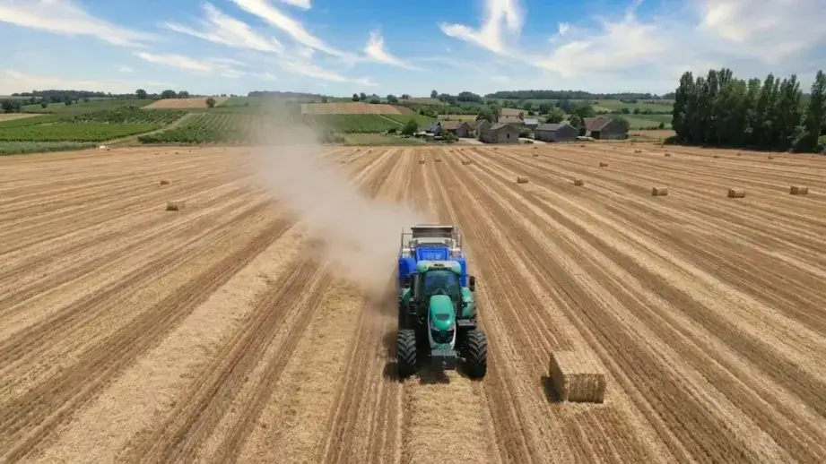
La prueba de 20 fardos es obligatoria tras cualquier ajuste del anudador. La inspección estática del mecanismo confirma que los componentes están en la posición correcta, pero solo el empacado real bajo carga de compresión y a velocidad de operación revela si la sincronización produce la formación correcta de nudos en el ciclo dinámico. Realice la prueba a la velocidad de avance y con la densidad que utilizará en la producción, no a velocidad reducida ni con la densidad mínima.
COMPROBACIÓN 1
COMPROBACIÓN 2
COMPROBAR 3
COMPROBAR 4
Cuando el ajuste no puede solucionar el problema
Si la prueba de 20 fardos sigue fallando después de completar correctamente los cinco pasos de ajuste, el problema radica en componentes desgastados y no en un ajuste incorrecto. Un ajuste correcto no puede compensar un gancho con una zona plana en la punta, un seguidor de leva desgastado más allá del umbral de medición o un brazo de aguja doblado que, por lo tanto, no puede alcanzar la posición de alineación especificada, independientemente de la posición de ajuste. En este punto, el componente defectuoso debe identificarse mediante una medición comparativa con las especificaciones y reemplazarse. Un mecanismo correctamente ajustado con componentes desgastados producirá resultados ligeramente mejores que antes del ajuste, pero no alcanzará el estándar de cero fallos de atado que se logra con componentes y ajuste correctos en conjunto.
Sincronización de la toma de fuerza y del anudador
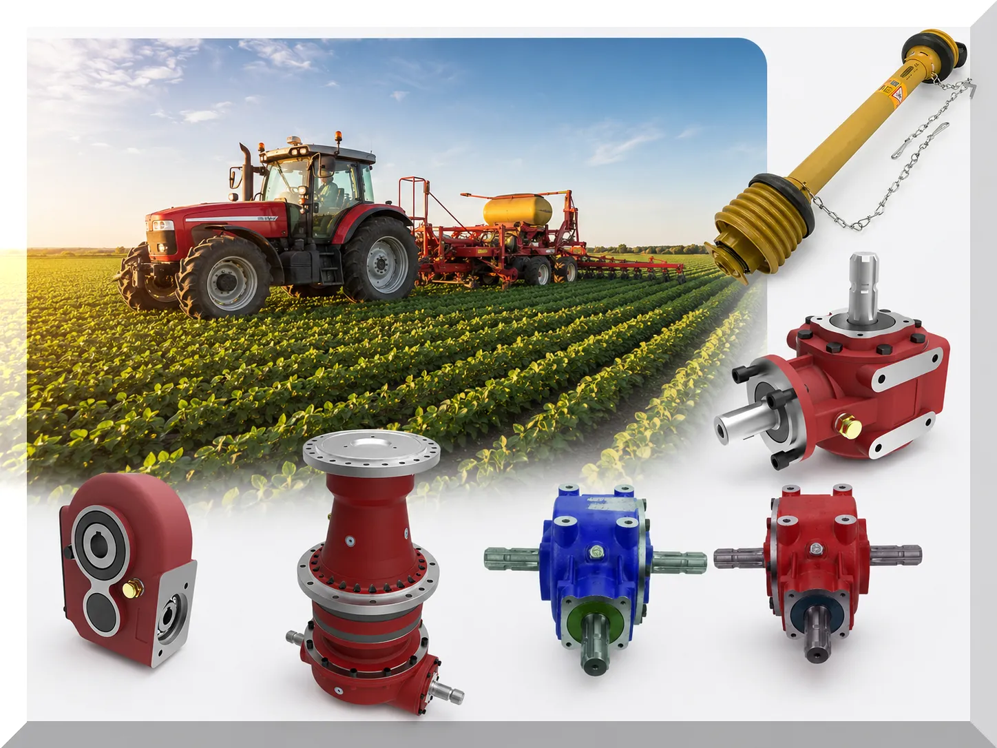
Especificaciones del eje de la toma de fuerza y de la caja de engranajes para la serie 9YF: Especificaciones de la caja de engranajes agrícola y del eje de la toma de fuerza (PTO).
Todas las especificaciones de sincronización del anudador están calibradas para una TDF de 540 rpm. A una velocidad de TDF significativamente inferior a la nominal, la sincronización del ciclo dinámico se modifica; un anudador ajustado correctamente a 540 rpm puede producir nudos defectuosos a 480 rpm. Mantener la velocidad nominal de la TDF es un requisito previo para la fiabilidad del anudador. Especificaciones del eje de transmisión: Guía de dimensionamiento del eje de transmisión de la toma de fuerza y de la junta homocinética.
Preguntas frecuentes: Ajuste del anudador de la empacadora cuadrada
Soporte técnico para el ajuste del anudador en su modelo 9YF
El ajuste del anudador requiere especificaciones específicas del modelo. Contáctenos con su Modelo 9YF Número y número de serie, y le proporcionaremos los valores correctos de especificación de tiempo y asistencia para cualquier problema de ajuste del anudador.
Editor: Cxm


