The Round Baler Drive Chain System: Five Circuits, Five Failure Points
A round baler contains multiple independent chain drives, each serving a different function in the baling process and each subject to different load conditions, contamination exposure, and wear rates. Most operators who think about “baler chain maintenance” are thinking of one chain — typically the most visible one. In practice, every chain in the baler’s drive system requires individual inspection, because failure in any one of them stops the baler as completely as any other.
#2 cause
Drive chain failure ranks as the second most common cause of mid-season round baler downtime after belt problems — ahead of bearing failure, pickup system issues, and hydraulic problems in most service records from agricultural dealers
3–5 kali
Higher emergency service cost for a chain failure in the field versus planned chain replacement during pre-season maintenance — accounting for emergency parts sourcing, labor, and the lost hay production time during the repair window
8 hrs
Maximum interval between chain lubrication applications during active baling in normal conditions — reduced to every 4 hours in wet, abrasive crops or sandy soil conditions where contamination accelerates chain wear
| Drive circuit |
Typical chain size |
Load level |
Contamination exposure |
Primary failure symptom |
| Pickup reel drive |
#60 or #80 |
Sedang |
Sangat Tinggi |
Crop not feeding cleanly; pickup reel stops or slows under load |
| Stuffer/feeder drive |
#80 |
Tinggi |
Tinggi |
Crop not entering chamber; characteristic slapping sound from stuffer area |
| Main chamber drive |
#80 or #100 |
Sangat Tinggi |
Sedang |
Bale not forming; grinding or knocking from drive side of baler |
| Net/twine wrap drive |
#60 |
Rendah |
Rendah |
Wrap material won’t feed; intermittent wrap failures; net/twine tears |
| PTO/gearbox input chain (beberapa model) |
#100 or #120 |
Sangat Tinggi |
Sedang |
Complete baler stop; loud crack at chain separation followed by silence |
Before any chain inspection: disengage PTO completely and wait for all rotating components to stop. A round baler’s drive train contains significant stored kinetic energy in spinning rollers, belts, and drive shafts. The PTO shaft can rotate for 10–20 seconds after the tractor PTO is disengaged at field operating RPM. Never reach into any chain or belt area until the forage baler is visually confirmed to be at complete standstill with the PTO disengaged and the tractor in park. Chain and belt injuries at baler maintenance are documented every season — every one of them was preventable.
Chain Wear Measurement: The 12-Link Method and When It Says Replace
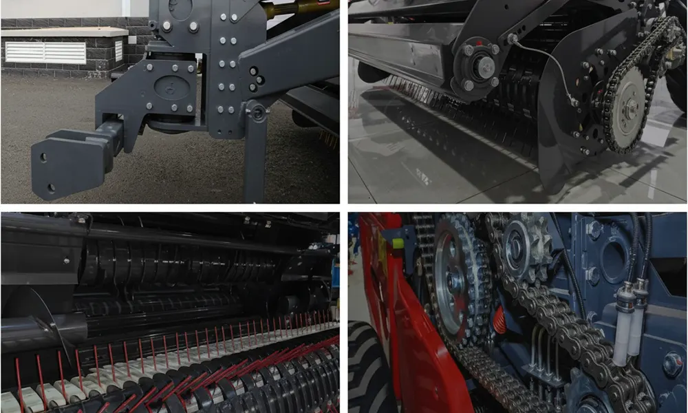
Agricultural roller chain wears through two simultaneous mechanisms: the link pins elongate from the compressive load at each sprocket engagement, and the bushings and rollers wear down from the abrasion of soil, crop debris, and metal-on-metal contact in the absence of adequate lubricant. The result is chain “stretch” — an increase in the effective pitch (pin-to-pin distance) that causes the chain to ride higher on sprocket teeth rather than seating in the tooth valleys. Beyond a critical elongation point, the chain begins to skip, load unevenly on the sprocket teeth, and accelerate both sprocket wear and chain fatigue toward sudden failure.
The 12-Link Measurement — Step-by-Step Protocol
1
Lay the chain on a flat, clean surface. Remove a section of chain from the baler (or measure on the sprocket with the baler stationary and locked out) with a minimum of 14 links visible. Wipe the chain clean so pin centers are clearly visible. Chain measured with dirt on the pins produces inaccurate readings because the caliper or tape measure seats against the dirt rather than the pin surface.
2
Align your measuring reference to the center of one pin — this is Link 1. Use a set of digital calipers for accuracy above a steel ruler; the caliper’s contact point should touch the center of the pin face. Mark this position or hold the zero of the calipers at this point.
3
Measure to the center of the 13th pin from your reference. You are measuring the span that covers 12 complete links (from pin 1 center to pin 13 center = 12 pitches of chain). Record this measurement to the nearest 0.01 inch or 0.25mm.
4
Compare your measurement to the replacement table below. If your reading equals or exceeds the “Replace At” value for your chain size, replace the chain before the next operating season. If you are within 0.10″ of the replacement value, plan replacement for this season even if technically in spec — the next season will put you over.
| Chain Size (ANSI) |
Pitch |
12-Link Nominal (new) |
Replace At (3% elongation) |
Typical baler application |
| #50 |
5/8″ (15.88mm) |
7.500″ |
7.725″ |
Wrap system drives, light duty applications |
| #60 |
3/4″ (19.05mm) |
9.000″ |
9.270″ |
Pickup drives, wrapper drives, lighter conveyor chains |
| #80 |
1″ (25.40mm) |
12.000″ |
12.360″ |
Main drive chains, stuffer drives — most common baler heavy application |
| #100 |
1-1/4″ (31.75mm) |
15.000″ |
15.450″ |
High-load primary drives, PTO gearbox input chains |
| #80H (Heavy) |
1″ (25.40mm) |
12.000″ |
12.300″ (use 2.5% for heavy) |
Heavy series — thicker plates; replace at lower elongation threshold than standard series |
Finding your chain size: The ANSI chain designation is stamped on the side plates of the chain at approximately every 10th link — look for a number like “80” or “60” or “80H” embossed into the metal. On older chains, this marking may have worn off; in that case, measure the pitch directly (pin-center to adjacent pin-center distance) and identify the chain size from the pitch measurement table above.
Tension Adjustment: The Deflection Method for Every Chain Location
Incorrect chain tension is responsible for more chain and sprocket failures than incorrect lubrication. An over-tight chain — which is the more common error, because operators correctly associate slack chain with problems but incorrectly conclude that tighter is always better — places continuous lateral stress on the sprocket bearings, accelerates pin and bushing wear, and in severe cases bends the shaft on which the sprocket is mounted. An under-tight chain skips on sprocket teeth under load, creating impact loads that are 4–6× higher than the normal running load and causing accelerated fatigue failure at the link plates.
The Deflection Measurement — Correctly Done
With the PTO fully disengaged and the silage baler at a complete stop, locate the longest unsupported span of chain between two sprocket contact points. Press the midpoint of this span with your finger using light pressure — approximately 1–2 lbs of force (just the weight of your hand resting on the chain, not pushing). Measure the deflection from the straight-line position to the depressed position.
Use light finger pressure only. Pressing hard gives a false reading that makes a correctly-tensioned chain appear slack.
Target Deflection by Chain Span Length
Short span (12–18″ between sprockets): 1/4″ (6mm)
Medium span (18–30″): 3/8″ (10mm)
Standard span (30–42″): 1/2″ (13mm)
Long span (42″+): 5/8–3/4″ (16–19mm)
These are general guidelines. Always check the manufacturer’s specification for your specific baler model — some applications require tighter tolerances. The manufacturer spec supersedes the general guideline whenever it is available.
Over-tight chain: what it sounds and looks like. A chain tensioned 30%+ beyond the correct deflection target produces a whining or humming sound from the drive side of the baler during operation — the chain is vibrating like a guitar string under excess tension rather than running smoothly. The sprocket bearings on chains that have been running over-tight will feel significantly warmer than surrounding structure after 2+ hours of operation (test by touch after complete PTO stop). If you notice either symptom, immediately stop and re-measure tension with the deflection method — the tendency to “tighten it a bit more” when chain noise occurs is the single most common maintenance error that converts a chain tension issue into a bearing failure.
Chain Lubrication: Penetrating Oil vs Surface Grease, Application Points, and Intervals
The most important lubricant-related fact about roller chain: the wear that shortens chain life occurs between the pin and bushing, inside the link — not on the chain’s outer surface. A chain that is coated with grease on the outside but has no lubricant reaching the pin-bushing interface will continue to wear at essentially the same rate as an unlubricated chain, because the external lubricant never reaches the internal surface where it is needed. Understanding this dictates both the lubricant type and the application method that actually extends chain life.
LUBRICANT TYPE COMPARISON FOR BALER CHAIN
Penetrating chain oil
(SAE 30 or dedicated chain lubricant)
Correct choice for most applications. Low viscosity allows the oil to flow by capillary action into the pin-bushing gap and between link plates where wear occurs. Apply to the chain on the slack (return) side of the drive, near a sprocket, with the baler running at idle PTO speed — the bending action as the chain wraps the sprocket draws the fresh oil into the internal components. SAE 30 motor oil is an adequate substitution when a dedicated chain lubricant is not available; it is not as effective as a low-viscosity penetrating chain lube but provides meaningful protection over no lubrication. Apply until the chain surface shows a continuous oil film — excess oil flings off during operation; under-application leaves the internal components dry.
Bearing grease
(NLGI #2, chassis grease)
Correct for grease zerks on sprocket hubs — not for the chain itself. Sprocket hub bearings are lubricated with grease through the hub’s grease zerks; this is correct and necessary. Applying bearing grease to the chain links creates a thick adhesive layer that catches and holds crop debris, grit, and soil against the chain’s outer surface, accelerating abrasive wear and preventing penetrating lubricants from reaching the internal components during subsequent lubrication. Do not apply bearing grease to roller chain. The confusion occurs because both are called “lubrication” — they serve different components with different requirements.
WD-40 and penetrating solvents
Not a chain lubricant — a displacement solvent. WD-40 displaces moisture and loosens rust; its lubricating film evaporates within 2–4 hours under operating temperatures, leaving the chain dry. It is useful for freeing a stiff link or cleaning rust from a chain that will then receive proper lubricant, but using it as the sole chain lubricant during operation provides no meaningful wear protection. Its very low viscosity means it also cannot stay in the pin-bushing gap under operational load.
Lubrication interval by operating condition
Normal hay in dry conditions (low dust, low moisture): every 8 hours of operation. Cover crop or straw in sandy or dusty conditions: every 4 hours. Wet or green crop (baleage, silage): every 4 hours (moisture washes lubricant from chain faster). High ambient temperature above 95°F: add an extra application at the end of the day after the chain has cooled, as heat-thinned lubricant migrates off the chain during operation at elevated temperatures.
Automatic chain oilers — worth it or not?
A drip-type automatic oiler metered to release 2–4 drops per minute onto the chain’s slack side during operation maintains the internal lubrication film without operator attention. University agricultural engineering research consistently shows that automatically oiled chains in abrasive conditions last 2.5–3.5× longer than manually oiled chains on equivalent lubrication schedules, because the oiler provides continuous lubrication at the operating temperature when lubricant flow and penetration are best. For PTO and drive chain specifications compatible with automatic oiler retrofitting, see Spesifikasi komponen gearbox pertanian dan sistem penggerak PTO..
Master Link and Connecting Link: The Most Common Field Repair Done Wrong
The master link (also called the connecting link) is the removable link that allows a chain to be separated without a chain breaker tool. In a round baler, master links are present in most chain circuits for serviceability, and they are also the chain’s weakest point when incorrectly installed. An improperly installed master link clip will back off the link under vibration and release the connecting plate — separating the chain with no audible warning — typically within the first 30–60 minutes of operation after installation.
The Direction Rule — The One Thing That Cannot Be Wrong
A clip-type master link consists of two side plates, two connecting pins, and a spring clip (shaped like the letter C). The spring clip slots into grooves at the end of both pins to retain the outer side plate. The clip has a closed end (the rounded bump of the C) and an open end (the two tips of the C).
RULE: The closed, rounded end of the clip must face the direction the chain travels. When the chain moves in the operating direction, it tries to push the closed end tighter into the pin groove — the clip self-tightens. If the clip is installed with the open end facing the direction of travel, chain movement tries to pry the open tips away from the pin grooves — the clip progressively loosens and eventually flies off, releasing the connecting plate and separating the chain.
Field Installation Protocol
Langkah 1: Confirm chain travel direction before touching the master link. Trace the chain from drive sprocket to driven sprocket; the chain travels from the drive sprocket’s output side toward the driven sprocket.
Langkah 2: Insert the connecting pins through both side plates and the chain ends being joined.
Langkah 3: Orient the spring clip with the closed (rounded) end pointing in the direction of chain travel.
Langkah 4: Seat the clip in both pin grooves using pliers — not a screwdriver. A screwdriver can spring the clip or unseat it from the groove while appearing installed.
Step 5: Visually verify the clip is fully seated in both grooves before running the chain. A partially seated clip feels tight but will release under vibration.
The rivet-type master link is the correct choice for high-load applications. For the main chamber drive chain (#80 or #100) and the PTO gearbox input chain where tensile loads are highest, a rivet-type master link (permanently installed with a chain rivet tool) is significantly stronger than the clip type and eliminates the clip-direction failure mode. The trade-off: a riveted link requires a chain breaker and punch to remove, which requires the dedicated tool in the field kit. For balers operated in commercial custom baling scenarios where drive chains are subjected to peak loads daily, equip the field kit with a chain breaker and use rivet links on the two highest-load circuits.
Chain Replacement: Matching New to Old and Breaking In Correctly
Chain replacement seems straightforward: remove the old chain, install the new one. The two errors that prevent a new chain from achieving its expected service life are both invisible at installation — mixing old and new chain in the same drive loop, and running new chain on worn sprockets. Both destroy a new chain far ahead of its designed replacement interval.
Never mix new and old chain in the same drive loop
A roller chain that has elongated 2–3% has larger effective pin diameters and longer pitch than a new chain. When a new section is spliced into an old chain, the new links contact the sprocket teeth at different points than the old links — the new links seat in the tooth valleys while the old links ride on the tooth tips. This alternating contact pattern creates a rocking motion in the chain as it traverses each sprocket, generating shock loads that crack link plates at the transition between old and new. The correct replacement protocol: replace the entire chain loop at one time, not sections. If only one section of the chain has failed, inspect the rest of the loop for elongation — if any section tests at the replacement threshold, replace the full loop.
Break-in protocol for new chain
New chain undergoes rapid initial elongation (called “seating elongation”) as the link components conform to each other under load. This normal elongation of 0.2–0.4% occurs in the first 2–4 hours of operation. During break-in: (1) run at reduced PTO speed (approximately 75% of operating speed) for the first hour; (2) stop and check tension after 30 minutes — readjust if deflection has increased; (3) re-lubricate after the first hour to ensure the seating wear debris is flushed from the chain before it acts as an abrasive. After 4 hours of break-in, re-check tension and set to final specification, then log the measured 12-link dimension as the baseline for future wear tracking.
Pre-Season Chain Inspection: The 30-Minute Audit That Pays for Itself
A complete baler chain inspection can be completed in 25–35 minutes by one person with basic tools — a set of digital calipers, a penetrating chain lubricant, a flashlight, and a chain wear gauge or ruler. The cost of this inspection in time and materials is approximately $15–$20. The cost of a single chain failure in the field during prime baling weather is $150–$600 in parts and service plus multiple hours of lost production. This is the most favorable cost-benefit ratio of any maintenance investment in the hay operation.
PRE-SEASON CHAIN AUDIT — Complete Checklist (estimated 30 minutes)
STEP 1 — OPEN ACCESS (5 minutes)
☐ Remove all drive chain guards and side covers. You cannot inspect what you cannot see. On most round balers, this means removing 6–14 bolts depending on model. Keep the bolts in a container by the baler.
☐ Clean each chain and surrounding area with a brush and compressed air if available. Crop dust and chaff conceals stiff links, rust, and wear marks that are critical to find during inspection.
STEP 2 — MEASURE EVERY CHAIN (10 minutes)
☐ Identify ANSI chain number for each circuit (stamped on side plates).
☐ Measure 12-link span on each chain. Record measurements — compare against replacement table. Replace any chain at or within 0.10″ of the replacement specification.
☐ Check for stiff links by flexing each chain section by hand. A link that resists bending or makes a grinding sound is seized with rust — replace the full chain loop if more than 2 stiff links are found.
STEP 3 — INSPECT SPROCKETS (7 minutes)
☐ Run your finger across the sprocket tooth profiles on every driven sprocket. A healthy sprocket tooth has a straight face with a pointed tip — like a shark tooth. A worn sprocket tooth curves forward — the tip hooks like a fishhook. Replace any sprocket showing the hooked profile.
☐ Grease all sprocket hub zerks until fresh grease appears at the seal. Worn hub bearings allow lateral movement of the sprocket that creates chain misalignment and accelerated link plate wear.
STEP 4 — TENSION AND MASTER LINKS (5 minutes)
☐ Check tension on every chain using the deflection method. Adjust any chains outside the specified deflection range.
☐ Locate and visually inspect every master link clip. Confirm all clips are fully seated in both pin grooves and oriented with the closed end facing the chain’s direction of travel. Replace any clip that shows wear, corrosion, or deformation.
STEP 5 — LUBRICATE AND CLOSE (3 minutes)
☐ Apply penetrating chain oil to every chain with a continuous film along the upper and lower runs of each loop. Allow 3–5 minutes for oil to wick into the internal link components before reinstalling guards.
☐ Reinstall all guards and covers. Run the baler at PTO idle for 2–3 minutes before the first baling pass to confirm all chains are operating smoothly before entering a windrow.
The complete seasonal maintenance schedule — including the full pre-season inspection protocol covering bearings, belts, hydraulics, and the electrical system in addition to chains — is in the daftar periksa perawatan musiman mesin pengepak jerami bundar. Wear item replacement intervals for all baler components are in the round baler parts and wear item replacement guide.
Sprocket Wear: The Component That Destroys New Chain Fastest
Replacing a worn chain while leaving the worn sprocket in place is one of the most common and most costly maintenance errors in baler drive train service. It is also one of the least visible errors, because a sprocket that looks “okay” to casual inspection may have tooth wear that is destroying new chain at 2–3× the normal rate.
The Hooked Tooth Mechanism — Why It Kills New Chain
A new sprocket tooth has a straight face from root to tip; the chain’s roller seats cleanly in the tooth valley at the tooth root and climbs the straight tooth face as the chain wraps around the sprocket. As the sprocket wears, material is progressively removed from the tooth’s driving face (the face that pushes the chain). The tip of the tooth remains while the base of the driving face wears back — the tooth develops an overhang or “hook.” A new chain’s rollers, sized for the new tooth geometry, contacts the hook tip rather than seating properly in the valley. Each hook contact applies an impact load rather than a smooth engagement load — this is what causes the cracking of new link plates that results in chain failure in 1/3 the normal service life.
The Replacement Decision
Replace the sprocket when: Tooth tips feel hooked to your fingernail (you can feel a forward-curving overhang when you run your fingertip over the tooth tip from back to front); tooth thickness at the pitch diameter is reduced by more than 25% from the original profile; any tooth is chipped, cracked, or visibly deformed.
Aturan praktisnya: When replacing a #80 or #100 main drive chain (the highest-load applications), evaluate the sprockets simultaneously and replace both if there is any doubt. The cost of a new #80 sprocket ($15–$45) versus the cost of a new #80 chain destroyed in half its normal lifespan ($35–$85) is not a difficult comparison. The troubleshooting guide for drive system failures — including the symptoms that distinguish worn sprocket from worn chain from incorrect tension — is in the panduan pemecahan masalah mesin pengepak jerami bundar.
For round baler configurations with extended drive chain service intervals and sealed lubrication systems on primary drive circuits, and for chain and sprocket component specifications by baler model, visit our model mesin pengepak jerami bundar.
Round Baler Chain Maintenance FAQs
How do I know if my baler chain is stretched too much to keep running?+
The 12-link measurement is the definitive test, but two field symptoms indicate a chain approaching or past its service limit before you measure. First, the chain visibly “sags” between sprockets beyond the normal tension deflection — sagging to 3/4 inch or more in a standard medium span means the chain has exceeded stretch tolerance and the tensioner has run out of adjustment range. Second, the chain makes an irregular slapping or skipping sound when the drive is engaged at normal PTO speed — this is the chain briefly losing engagement with the sprocket teeth under load and re-engaging with an impact. Both symptoms indicate a chain at or past replacement time. Running the chain in this condition risks a complete separation under peak load — typically at the moment of bale formation when the chamber drive is under maximum compression force. Measure immediately and replace if at or above the 3% elongation threshold from the replacement table.
Can I use WD-40 to lubricate baler chains?+
WD-40 is a penetrating solvent and moisture displacer, not a chain lubricant. It is useful for two specific purposes in chain maintenance: freeing a seized or rusty stiff link by soaking the link for 10–15 minutes before working the link back and forth, and cleaning chain surfaces before applying actual lubricant. For ongoing chain lubrication during operation, WD-40 is not effective — it evaporates under operating temperatures within 1–2 hours and provides no meaningful protection for the pin-bushing interface during the operating period. The correct lubricant is SAE 30 motor oil, a dedicated chain oil, or a chain and cable lubricant spray with at least 30W viscosity. If you are in the field with only WD-40 and no chain oil for an emergency re-lubrication, apply it and then prioritize acquiring proper chain oil before the next extended baling session. WD-40 is better than nothing for a brief emergency but significantly inferior to any actual lubricating oil.
My baler chain keeps jumping off the sprocket — what causes this?+
Chain jumping off a sprocket has three primary causes, each diagnosable by where and when the jumping occurs. First and most common: chain too loose. A slack chain can bounce off the sprocket teeth during the impact of engaging a sudden load — tighten to the correct deflection specification and re-evaluate. Second: sprocket misalignment. Two sprockets in the same drive loop must be on the same plane (aligned) to within approximately 1/16 inch — a misaligned sprocket causes the chain to try to run diagonally and will walk off the tooth face. Check alignment with a straightedge across both sprocket faces. Third: sprocket teeth are worn to the hooked profile. A hooked sprocket tooth cannot retain the chain roller in the normal seating position — under load the roller climbs over the hook tip rather than staying in the valley, and the chain disengages from the sprocket. Inspect tooth profile and replace the sprocket if hook wear is visible. Running a new tight chain on a hooked sprocket will not solve the jumping problem — the sprocket must be replaced.
What is the difference between #60 and #80 chain and how do I identify which my baler uses?+
#60 and #80 are ANSI roller chain designations where the number refers to the chain’s pitch in eighths of an inch: #60 = 6/8″ = 3/4″ pitch, and #80 = 8/8″ = 1″ pitch. The larger number means a larger, stronger, heavier chain. They are NOT interchangeable — a #80 chain will not fit on a #60 sprocket and vice versa because the sprocket tooth spacing is sized to match the chain pitch. To identify which chain is on your baler: look at the side plate of the chain for a stamped number (60, 80, 80H, etc.) which is the ANSI designation. If the number is worn off, measure the pin-to-pin pitch directly: if it measures approximately 3/4 inch (0.750″) it is #60; if it measures approximately 1 inch (1.000″) it is #80. Take a short length of old chain to the parts counter when ordering replacement — matching by measurement is safer than trying to recall a model number. #80 is by far the most common chain on round baler main drives, but the wrap system and pickup drive are often #60 on the same machine, so verify each circuit separately.
How often should I replace baler chains as a scheduled maintenance item?+
Chain replacement should be driven by the wear measurement (12-link test at or past the 3% elongation threshold) rather than a fixed time or bale-count interval, because actual chain life varies dramatically with lubrication, crop type, dust conditions, and operating hours per season. A well-lubricated chain on clean hay in dry conditions may achieve 3–5 seasons before reaching the replacement threshold; the same chain on silage in sandy conditions with inconsistent lubrication may need replacement annually. The practical approach: measure every chain at the pre-season inspection every year. Chains that are below the replacement threshold but within 0.10″ of it should be budgeted for replacement during that season — they will reach the threshold during the season if they don’t already meet it. Chains that are significantly below the threshold need inspection but not immediate replacement. This measurement-driven approach prevents both premature replacement (waste) and running chains past their safe operating life (failure risk).
Can I extend chain life beyond normal intervals through better maintenance?+
Yes — significantly. The two maintenance practices with the greatest documented impact on chain service life are lubrication frequency and contamination control. Research from agricultural engineering programs shows that chains maintained on a 4-hour lubrication schedule (twice the standard 8-hour interval) in abrasive field conditions last 60–80% longer than identically stressed chains on the 8-hour schedule. The additional lubrication cost ($10–$15/season in chain oil) is insignificant compared to the extended chain life value. Contamination control — primarily keeping chain guards in place so crop debris and soil cannot pack into the chain links during operation — is the second highest-impact practice. Operators who remove chain guards “for convenience” and don’t replace them expose their chains to continuous abrasive packing that eliminates lubrication film within an hour of application. Running without guards should be considered the equivalent of running without lubrication from a chain wear perspective. Replacing worn sprockets simultaneously with chain replacement is the third practice — as described in this guide, new chain on a hooked sprocket will not achieve more than 30–50% of its rated service life regardless of lubrication quality.
Editor: Cxm